Horizontal, through the wall installation, Horizontal through-the-wall installation, Figure 3 – DuraVent FasNSeal Single-Wall User Manual
Page 8
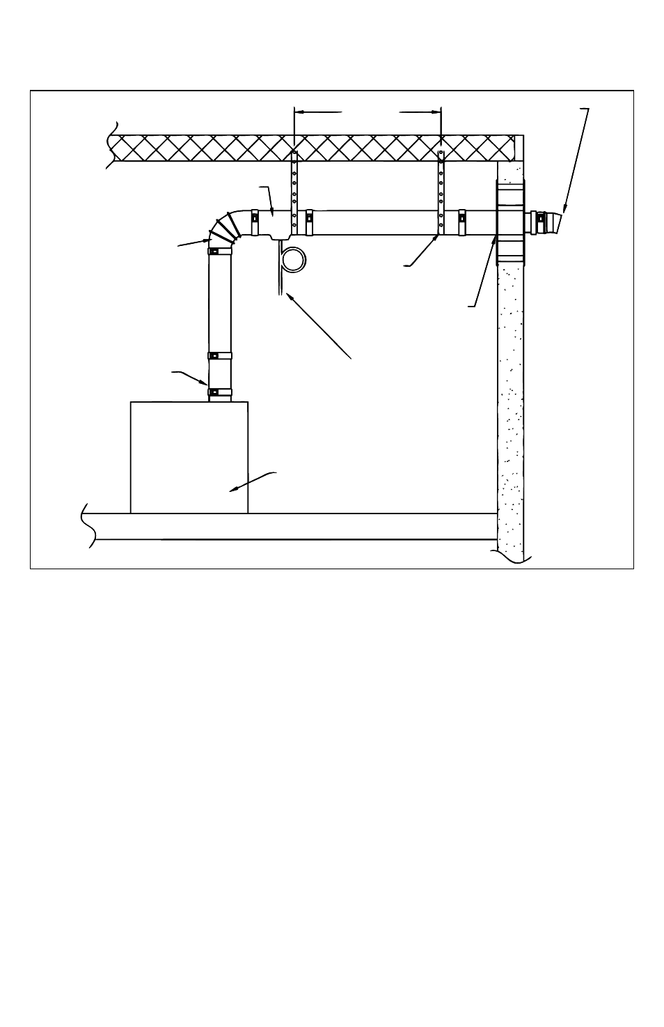
Horizontal Through-The-Wall Installation
TERMINATION TEE OR
BIRD SCREEN
6’ MAx.
HORIZONTAL DRAIN TEE
OR DRAIN FITTING WITH TEE
HANGER STRAP
WALL THIMBLE
TO DRAIN DISPOSE
OF CONDENSATE
ACCORDING TO
LOCAL CODES
APPLIANCE ADAPTER
APPLIANCE
ELBOW
8
HORIzONTAL, THROUgH THE
WALL INSTALLATION
• For a typical Horizontal Through the Wall
installation, refer to Figure 3. When venting
through a sidewall, terminate the system not
less than 12” (.3m) above the ground and
above the snow line in geographical areas
where snow accumulates. The termination
area must be kept clear of snow and ice
at all times.
•Terminate the system at least 7’ (2.1m) above
a public walkway or driveway, no less than
6’ (1.8m) from the combustion air intake
of any appliance or 3’ (.9m) from any other
building opening, gas utility meter, service
regulator or the like. It also shall terminate
at least 3’ (.9m) above any forced air inlet
within 10’ (3.1m) and shall terminate at least
4’ (1.2m) below, 4’ horizontally from or 1’
(.3m) above any door, window, or gravity
air inlet into any building as provided in the
National Fuel Gas Code ANSI Z223.1/NFPA
54 or the International Fuel Gas Code. Proper
judgement may require greater distances
depending on the size of the equipment
installed or to allow for snow drifting or
falling from overhead roofs or trees. The
termination should be far enough away from
trees, shrubs or decorative items to
prevent damage.
•The total vent length from the appliance flue
collar to the outside termination shall not
be greater than specified in the appliance
manufacturer’s instructions.
•A horizontal installation shall have a slope
(upwards away from the appliance for
Figure 3