Figure 10 figure 9 figure 8 – DuraVent FasNSeal Single-Wall User Manual
Page 12
12
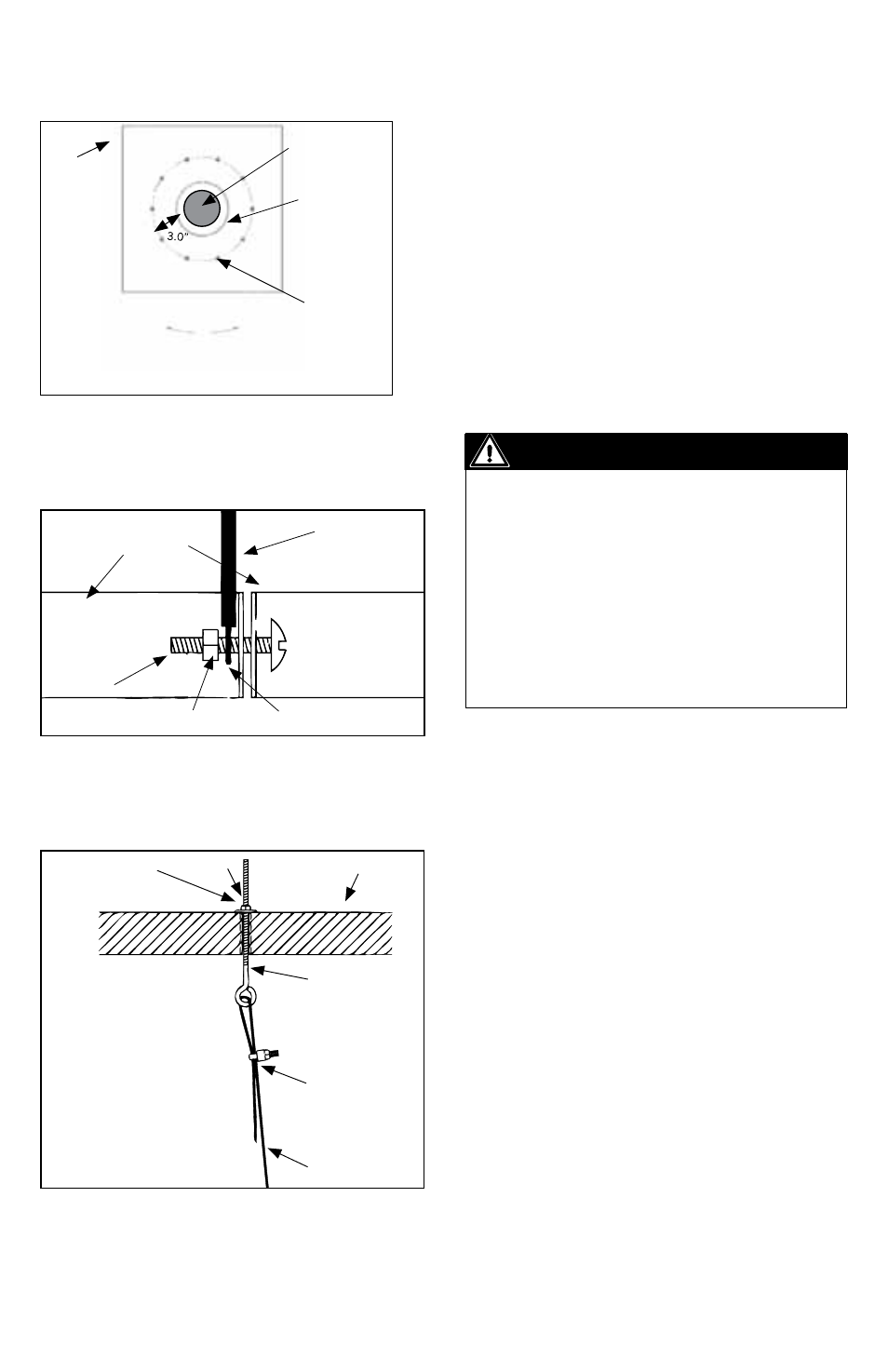
of the vent will provide some lateral stability
to the system. Additional ¼” threaded holes
will have to be drilled around the vent for
the anchors. These smaller holes should
be evenly spaced around the diameter of
the central hole. Refer to Figure 8 for the
recommended pattern.
Install ¼” eye bolts with washers and nuts.
These will be used to anchor the tension
wires to the support plate.
Figure 10
Figure 9
Figure 8
1. Inspect and verify the structural integrity of
the chimney and chimney cap. The weight of
the vent will be resting on the chimney and
an unstable chimney may shift
and/or collapse.
2. Install a FasNSeal support clamp at the
base of the vent stack. The first support
clamp should be located directly below the
upper joint on the bottom most straight vent
length (Figure 7). Refer to Figure 9 for the
proper method of securing tension wires to
the FasNSeal support clamp. Do not fasten
the cable between the clamp half-shells. This
will prevent the clamp from gripping the vent
stack properly
3. Gradually lower the vent stack into the
chimney. Secure additional FasNSeal support
IMPORTANT
The loads, plate and cable thickness,
as well as the eyelet sizes specified in
these instructions are representative
and must be calculated for each
individual application.
Be sure to remember to connect the
condensate drain at the bottom of the
stack. Condensates must be directed to
a safe point of discharge.
DEGREES
BETWEEN HOLES
180° ÷ #CLAMPS
1/4"
HOLES
FASNSEAL
VENT LENGTH
STEEL
PLATE
1/2" HOLE
LARGER THAN
OTER WALL OF
VENT
TENSION WIRE
CLAMP HALFSHELL
EyELET
NUT
SCREW
teNSIoN WIre
CaBle ClaMp
1/4" eye Bolt
Steel plate
WaSher
Nut