Defining the tp-146 uxga/audio/data line receiver – Kramer Electronics TP-146 User Manual
Page 7
Defining the TP-145/TP-146
5
5
source (for example, a PC), fails to output video because it was not connected to
the display device when attempting to read its EDID.
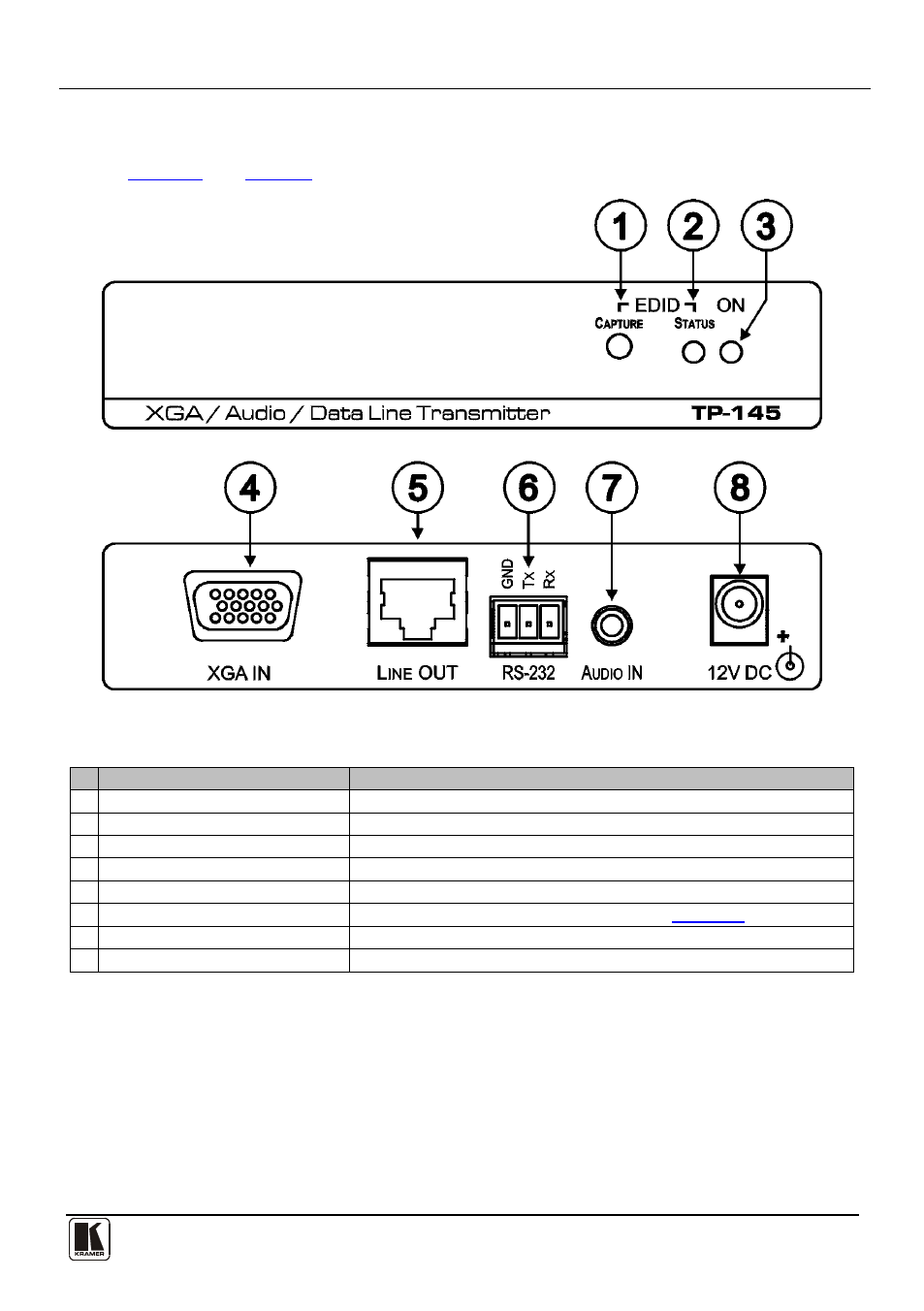
Figure 1: TP-145 XGA/Audio/Data Line Transmitter Front and Rear Panels
Table 1: TP-145 XGA/Audio/Data Line Transmitter Front and Rear Panel Features
#
Feature
Function
1
EDID CAPTURE Button
Press to capture the EDID
2
EDID STATUS LED
Lights Green when the EDID has been successfully captured
3
ON LED
Lights Green when the unit receives power
4
XGA IN 15-pin HD (F) Connector
Connect to the UXGA source
5
LINE OUT RJ-45 Connector
Connect to the LINE IN RJ-45 connector on the TP-146
6
RS-232 Terminal Block
Connect to the PC or the Remote Controller (see
Section 5.1
7
AUDIO IN 3.5mm Mini Connector
Connect to the analog audio source
8
12V DC Power Connector
Connect to the supplied +12V DC power adapter. Center conductor positive
4.2
Defining the TP-146 UXGA/Audio/Data Line Receiver
The TP-146 is a high-performance receiver that accepts the computer graphics
signal/audio/control data from the Kramer TP-145 via TP cabling at its RJ-45
LINE IN input. The TP-146 outputs a computer graphics signal, an unbalanced
stereo analog audio signal, a converted digital audio (S/PDIF) signal, and bi-
directional RS-232 control commands and data. The RS-232 interface makes it
possible to control virtually any device over a transmission range of up to 200m