Kramer Electronics TP-146 User Manual
Page 10
KRAMER: SIMPLE CREATIVE TECHNOLOGY
Connecting the TP-145 and the TP-146
8
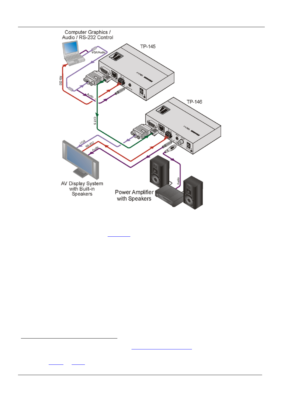
Figure 4: Connecting the UXGA/Audio/Data Line Transmitter/Receiver System
To connect the TP-145 and the TP-146 to create a TP transmitter and receiver
system, as illustrated in
1. On the TP-145, connect:
A UXGA source (for example, the graphics card on a laptop) to the
UXGA IN 15-pin HD (F) connector
An audio source to the AUDIO IN 3.5mm mini connector, for example,
using a Kramer C-GMA/GMA cable (VGA 15-pin HD (M) +Audio jack
to VGA 15-pin HD (M) +Audio jack)
An RS-232 cable with a 9-pin D-sub connector at one end to the laptop, and a
3 pin terminal block connector at the other end to the TP-145 RS-232 port
2. On the TP-146, connect:
The UXGA OUT 15-pin HD (F) connector to the AV display system
The S/PDIF AUDIO OUT RCA connector to a digital AV Receiver
1 Not supplied. The full list of Kramer cables is available fro
lternatively, you can connect a
UXGA source to the UXGA IN 15-pin HD (F) connector, and a separate audio source to the AUDIO IN 3.5mm mini connector
2 As defined in