3 connecting the remote connector, Connecting the remote connector, Figure 3: remote terminal block connector – Kramer Electronics VS-24xl User Manual
Page 11: Ction 5.3
8
VS-24xl - Operating the VS-24xl
5.3
Connecting the Remote Connector
In addition to its automatic switching function, the VS-24xl can operate as a
remote controlled video and audio 2x1 switcher, by connecting contact closure
switches to the appropriate REMOTE input terminal block connector pins thus
forcing the routing of one of the two inputs to the output by remote control.
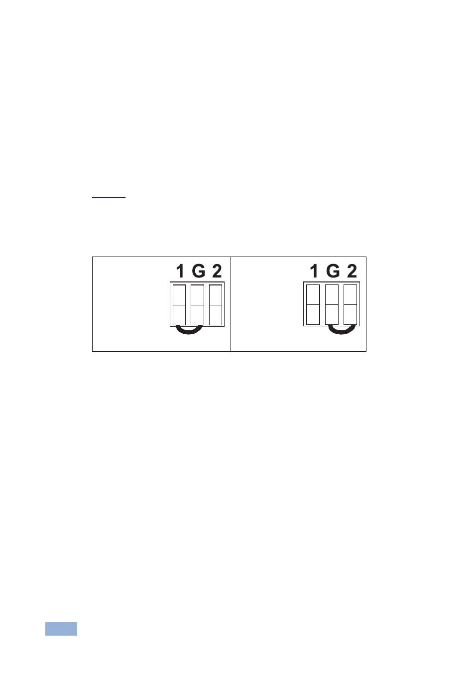
To do so, connect the appropriate REMOTE input terminal block connector pins to
a contact closure switch and release the MODE IN=AUTO button. For example, as
illustrates, to route remote input 1 to the output, connect PIN 1 to the
Ground. Similarly, to route remote input 2 to the output, connect PIN 2 to the
Ground. Do not connect both the remote input 1 and the remote input 2 to the
Ground simultaneously.
Route input 1
to the output,
by attaching
PIN 1 to the
Ground:
Route input 2
to the output,
by attaching
PIN 2 to the
Ground:
Figure 3: Remote Terminal Block Connector
When both input 1 and input 2 are connected, the (valid) signal from remote input
1 routes to the output. However, you can force the routing of remote input 2 to the
output by attaching PIN 2 to the ground. If no input is present on remote input 2,
you can even force the routing of the output from remote input 2 (displaying a
blank screen) by attaching PIN 2 to the ground.