Figure 1: vp-311dvi automatic dvi/audio switcher – Kramer Electronics VP-311DVI User Manual
Page 9
6
VP-311DVI - Overview
3.2
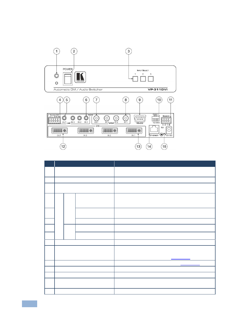
Defining the VP-311DVI Automatic DVI/Audio Switcher
This section defines the VP-311DVI.
Figure 1: VP-311DVI Automatic DVI/Audio Switcher
#
Feature
Function
1
IR Receiver
The red LED lights when receiving signals from the
Infrared remote control transmitter
2
POWER Switch
Illuminated switch for turning the unit ON or OFF
3
INPUT SELECT Buttons
Press the INPUT button (from 1 to 3) to select the input to
switch to the output
4
A
UD
IO
L
INE
BALANCED OUT
Terminal Block
Connector
Connects the balanced stereo audio output to a balanced
stereo audio acceptor
5
OUT 3.5mm Mini
Jack
Connect to an unbalanced stereo audio output
6
IN 3.5mm Mini Jack
Connect to unbalanced stereo audio inputs (from 1 to 3)
7
S
/P
DIF
OUT RCA Connector Connect to a digital audio (S/PDIF) output
8
IN RCA Connectors
Connect to digital audio (S/PDIF) inputs (from 1 to 3)
9
RS-232 9-pin D-sub Connector
Connect to the PC or the Remote Controller
10 PRIORITY SETUP DIP-switches DIP-switches for setup of the machine: DIPs 1, 2, 3 are
for setting the signal priorities, DIP 4 is for setting to the
manual or the AUTO mode (see
Section
11 REMOTE Terminal Block
Connects to a dry contact switch (see
Section
12 OUT DVI-I Connector
Connect to the DVI acceptor
13 IN DVI-I Connectors
Connect to the DVI sources (from 1 to 3)
14 ETHERNET Connector
Connect to the PC or other Serial Controller through
computer networking
15 12V DC
+12V DC connector for powering the unit