3 connecting to the vp-311dvi via rs-232, Connecting to the vp-311dvi via rs-232, Figure 5: crossed cable rs-232 connection – Kramer Electronics VP-311DVI User Manual
Page 13
10
VP-311DVI - Connecting the VP-311DVI
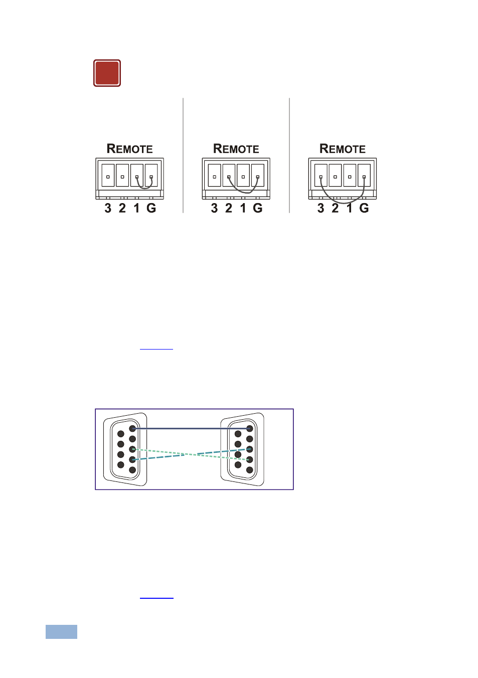
DO NOT Connect more than one PIN to the Ground PIN at the
same time
Figure 4: Connecting the Contact Closure Remote Control PINS
4.3
Connecting to the VP-311DVI via RS-232
You can connect to the unit via a crossed RS-232 connection, using for example,
a PC. A crossed cable or null-modem is required as shown in method A and B
respectively. If a shielded cable is used, connect the shield to pin 5.
Method A (
—Connect the RS-232 9-pin D-sub port on the unit via a
crossed cable (only pin
2
to pin
3
, pin
3
to pin
2
, and pin
5
to pin
5
need be
connected) to the RS-232 9-pin D-sub port on the PC.
Note: There is no need to connect any other pins.
Figure 5: Crossed Cable RS-232 Connection
Hardware flow control is not required for this unit. In the rare case where a
controller requires hardware flow control, short pin 1 to 7 and 8, and pin 4 to 6 on
the controller side.
Method B (
—Connect the RS-232 9-pin D-sub port on the unit via a
straight (flat) cable to the null-modem adapter, and connect the null-modem
!
To route IN 1 to the
output, temporarily
attach PIN 1 to
PIN G (Ground)
To route IN 2 to the
output, temporarily
attach PIN 2 to
PIN G (Ground)
To route IN 3 to the
output, temporarily
attach PIN 3 to
PIN G (Ground)
1
2
6
3
7
4
8
5
9
1
2
6
3
7
4
8
5
9
PC