E lectron ics, Matrix routing switcher – Kramer Electronics TailorMade User Manual
Page 5
5
K R A M E R
E lectron ics
MATRIX ROUTING SWITCHER
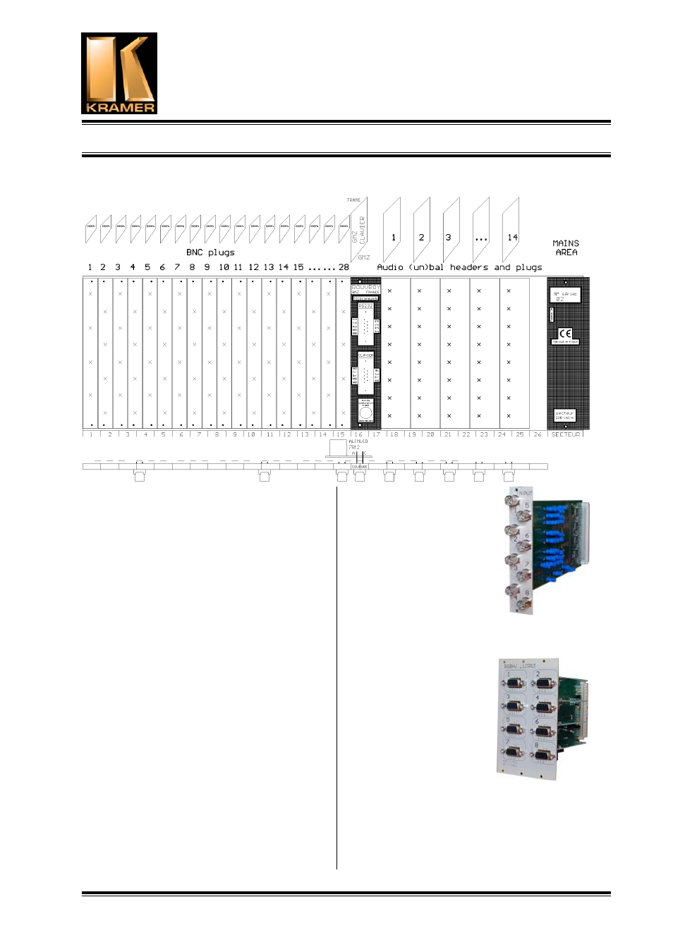
1.3 CREATING A MATRIX
The rear panel of the rack is 84 E wide, on 3RU
high. (E=5,08 mm). The mains, RS232 and RS422
plugs 12 E. So, the useful area for the audio, vidéo
et RGB is 72 E.
The BNC are shared by four, on vertical bands
which are 2,5 E wide, on 3RU.
We can house up to 28 vertical bands in this area,
i.e. 112 BNC plugs. So, we can realize a 56x56
video matrix, or a 48 X 64, 40 X 72, or 16 X 96 …
When more, the rack has to be 6RU high. Then the
total number of plugs rise to 224, and permits
important dimensions. With a 9 RU rack, the
number is 336, etc.
The stereo audio plugs are shared by eight, on 5 E
bands with 3RU. We can house 14 bands, i.e. 112
stereo audio plugs. For example, we can realize a
stereo balanced 56 X 56, etc.
In YC mode,the capacity the divided by two ; in
component mode, by three ; in RGBHV mode, by
five.
1.4 VIDEO SECTION
The video section in an area with cards including
the input and outputs plugs, the buffers, the
switchers, the outputs 75 Ohms amplifiers, and the
controllers. The input cards (called BME), and the
output cards (called BMS),
own a 41612 DIN connector
to get the power supply and
the service signals by the
internal rail.
Each cars has 8 BNC
connectors for in or out.
1.5 RGBHV
SECTION
RGBhv architecture is the
same as the video section :
Each card can support the
R, G, B, H or V, and is
simultaneously controlled.
The input and output
impedances is a 75 Ohms
on BNC or HD15, and the
bandwidth is 325 MHz
minimum.
1.6 AUDIO SECTION
The architecture of the audio path is different.
There is no module as for the video, but traditional
cards, directly connected on the internal bus. On
Kramer