Kramer Electronics VP-32K User Manual
Page 6
KRAMER: SIMPLE CREATIVE TECHNOLOGY
Your VP-32K 3x1 PC / Audio Switcher
4
4 Your VP-32K 3x1 PC / Audio Switcher
Figure 1 and Table 1 define the
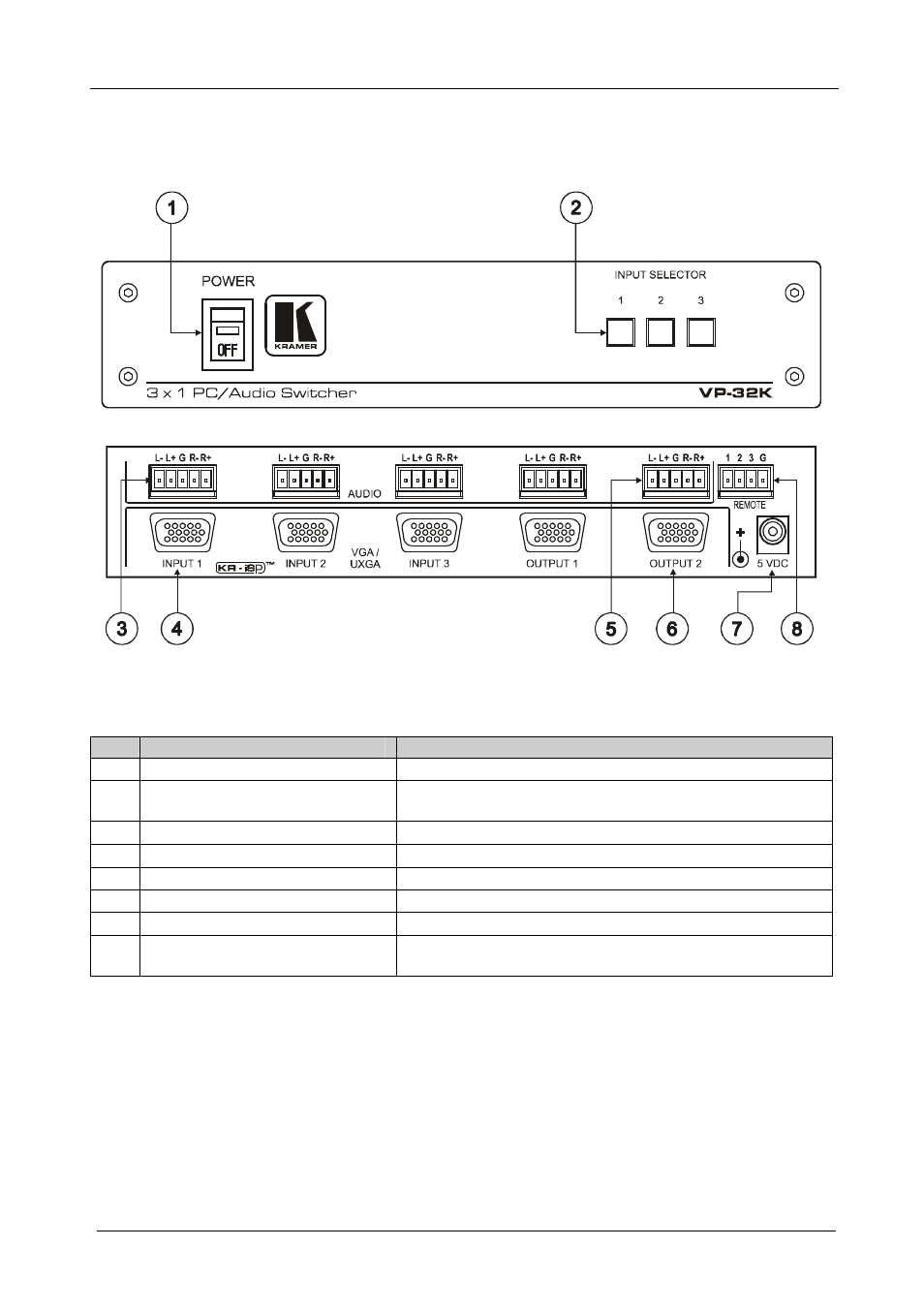
VP-32K 3x1 PC / Audio Switcher:
Figure 1: VP-32K 3x1 PC / Audio Switcher
Table 1: Front Panel VP-32K 3x1 PC / Audio Switcher Features
#
Feature
Function
1
POWER Switch
Illuminated switch supplying power to the unit
2
INPUT SELECTOR Buttons
Select the input (from 1 to 3) to switch to the outputs. The
selected button illuminates
3
INPUT Terminal Block Connector
Connect to the balanced stereo audio sources (from 1 to 3)
4
INPUT 15-pin HD Connectors
Connect to the VGA/UXGA sources (from 1 to 3)
5
OUTPUT Terminal Block Connector Connect to the balanced stereo audio acceptors (from 1 to 2)
6
OUTPUT 15-pin HD Connectors
Connect to the VGA/UXGA acceptors (from 1 to 2)
7
5V DC
+5V DC connector for powering the unit
8
REMOTE Terminal Block
Connector
Connect to contact closure switches (see section 5.2)