Kramer Electronics VM-1610 User Manual
Page 8
5.2 Getting to Know Your VM-1610 Amplifier
The KRAMER
VM-1610 is a full spec, state-of-the-art, 1:10 balanced stereo audio distribution
amplifier designed for studio and other demanding applications. The
VM-1610 has two inputs and
can be programmed by the user to function as a 1:10 or as a 2 x 1:5 DA. State-of-the-art Bi-Fet
amplifying circuitry and a high power discrete buffering system make the
VM-1610 an excellent
performer. All circuitry is active with no transformers thus ensuring hum-free and full bandwidth
operation. Front/rear panel features of the
VM-1610 are described in Figure 2 and Table
2
.
NOTE
For operation instructions refer to section
8
.
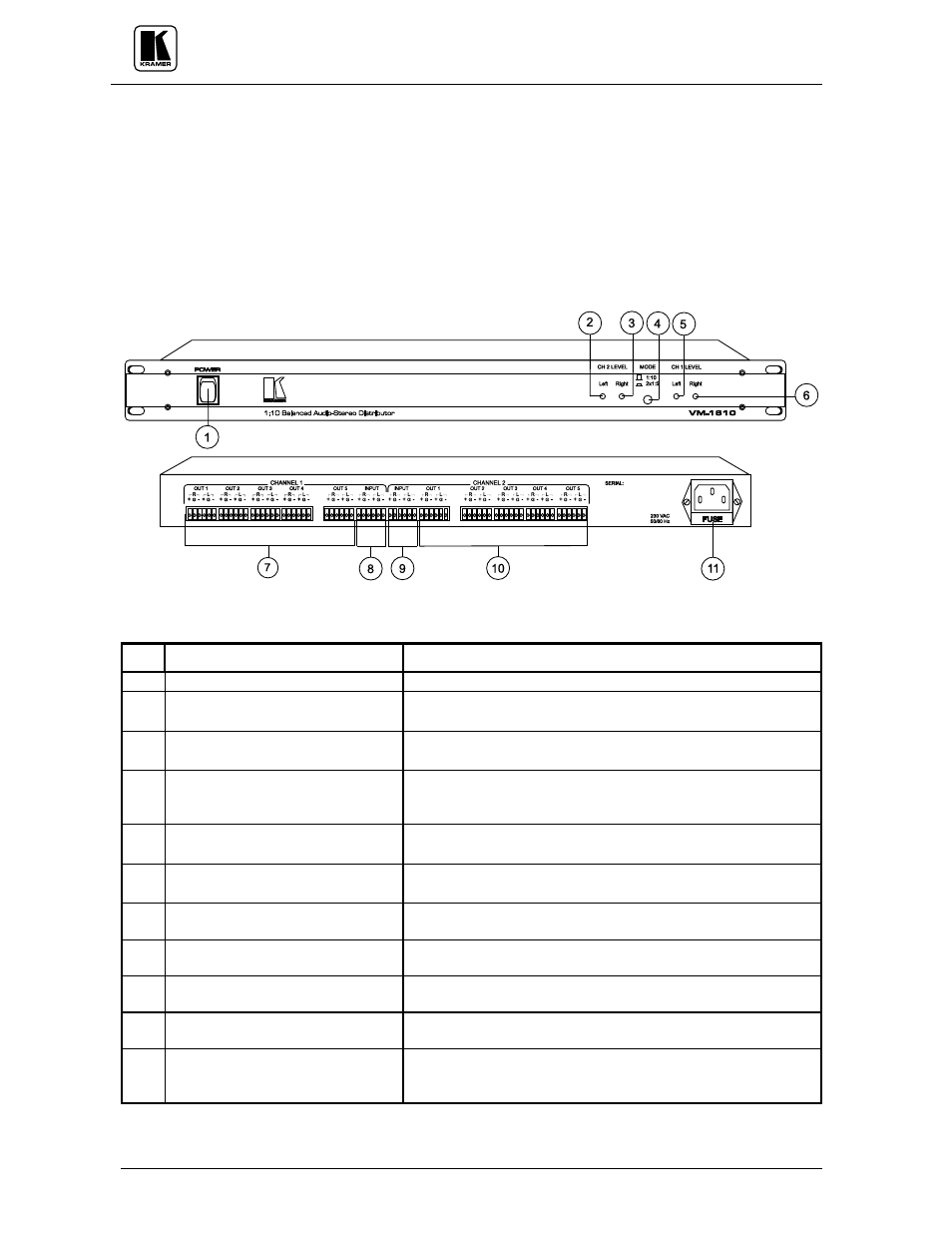
Figure 2: VM-1610 Front/Rear Panel Features
Table 2: VM-1610 Front/Rear Panel Features
No.
Feature
Function
1.
Illuminated
power switch
Supplies power to the unit.
2.
CH 2 LEVEL (Left) Gain trimmer Controls the left channel audio gain (the machine is factory
preset for accurate 1:1 signal transparency).
3.
CH 2 LEVEL (Right) Gain
trimmer
Controls the Right channel audio gain (the machine is factory
preset for accurate 1:1 signal transparency).
4.
MODE 1:10/2x1:5 selector
1:10 (released): Splits channel "1" input to all 10 outputs.
2x1:5 (pressed): Splits channel "1" and channel "2" " to
outputs "
1-5" of channels "1" and "2" respectively.
5.
CH 1 LEVEL (Left) Gain trimmer Controls the left channel audio gain (the machine is factory
preset for accurate 1:1 signal transparency).
6.
CH 1 LEVEL (Right) Gain
trimmer
Controls the Right channel audio gain (the machine is factory
preset for accurate 1:1 signal transparency).
7.
CHANNEL 1 OUT 1-5 (L,R)
terminal block connector
5 amplified and buffered audio outputs.
8.
CHANNEL 1 INPUT (L,R)
terminal block connector
Stereo audio balanced input.
9.
CHANNEL 2 INPUT (L,R)
terminal block connector
Stereo audio balanced input.
10.
CHANNEL 2 OUT 1-5 (L,R)
terminal block connector
5 amplified and buffered audio outputs.
11.
A 3-prong power connector/fuse
A 3-prong AC connector allows power to be supplied to the unit.
Directly underneath this connector, a fuse holder houses the
appropriate fuse.