Kramer Electronics VM-1610 User Manual
Page 10
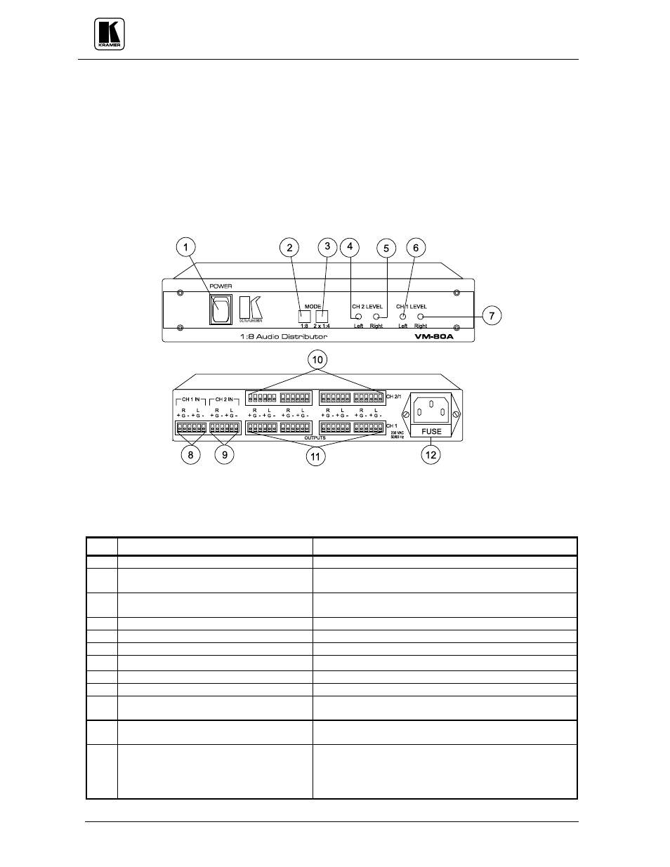
5.4 Getting To Know Your VM-80A Amplifier
The KRAMER
VM-80A is a Broadcast quality, state-of-the-art, balanced stereo audio distribution
amplifier designed for demanding applications, such as broadcast and production studios. The
VM-
80A has two balanced stereo audio inputs, each splitting the input source into four identical outputs.
The
VM-80A can function as a 1:8 DA or as two 1:4 DAs. It has trimmers on the front panel to fine
tune levels of each channel individually. Units in the 80 series come in a convenient, compact size
enclosure. Any two units fit side by side in a 19" rack using a special 1U-rack adapter. To achieve a
larger distribution system, the inputs of several machines may be looped by a parallel connection. For
signal enhancement and noise reduction, an audio signal processor may be inserted. Front/rear panel
features of the
VM-80A are described in Figure 4 and Table 4.
NOTE
For operation instructions refer to sections
8.1, 8.6
.
Figure 4: VM-80A Front/Rear Panel Features
Table 4: VM-80A Front/Rear Panel Features
No. Feature
Function
1.
Illuminated
Power Switch
Supplies power to the unit.
2.
1:8 operating mode touch switch
(Illuminated when pressed)
Splits channel "
1" input to all 8 outputs (channels
"
1"&"2")when pressed.
3.
2x1:4 operating mode touch switch
(Illuminated when pressed)
Splits channels "
1"&"2" inputs to output channels "1"&"2"
respectively when pressed.
4.
CH 2 LEVEL Left trimmer
Controls Channel "
2" (left) audio gain.
5.
CH 2 LEVEL Right trimmer
Controls Channel "
2" (Right) audio gain.
6.
CH 1 LEVEL Left trimmer
Controls Channel "
1" (left) audio gain.
7.
CH 1 LEVEL Right trimmer
Controls Channel "
1" (Right) audio gain.
8.
CH 1 IN (L,R) terminal block connector
Stereo audio balanced input.
9.
CH 2 IN (L,R) terminal block connector
Stereo audio balanced input.
10.
CH 2/1 OUTPUTS (L,R) terminal block
connectors
Amplified and buffered audio outputs.
11.
CH 1 OUTPUTS (L,R) terminal block
connectors
Amplified and buffered audio outputs.
12. Power Connector
A 3-prong AC connector allows power to be supplied to the
unit. Directly underneath this connector, a fuse holder houses
the appropriate fuse.