8 commissioning, 9 operation – Festo Линейный привод с датчиком перемещения DFPI User Manual
Page 4
3. Decide whether the air vent should be made on site or guided.
For guided air vent:
At the factory, the plug screw (
Fig. 11
3 ) is already mounted and the
DFPI-…C1V-P-A is thus prepared for guided air venting.
• If the plug screw has been dismounted: Reseal the connection for air vent on
site with sealing ring and plug screw (
Fig. 11
3 ) – tightening torque
13.5 Nm.
• Connect the tubing of the DFPI to the connections P and R (
Fig. 11)
.
Insert
the compressed air tubing into the push-in fitting up to the stop.
For on-site air venting directly at the DFPI:
• Seal the unused connection R (
Fig. 11
2 ) with the plug (accessories).
• Open the connection for on-site air vent by dismounting the plug screw
(
Fig. 11
3 ).
• Screw a filter nipple G¼ (for air vent without silencer) or a silencer G¼ (acces-
sories) into the connection for on-site air vent (
Fig. 11
3 ) – tightening
torque 4 Nm ± 10 %.
4. Connect tubing to the DFPI at the connection P by inserting the compressed air
tubing into the push-in fitting up to the stop.
In both cases:
5. Only in the unpressurized status: Check the reliable hold of the tubing connection
by lightly pulling on the tubing.
Pneumatic
connection
Description
Note
P
Supply port for operating pressure
Fig. 11
1
R
Only for guided venting:
exhaust port
Fig. 11
2
Fig. 12
6. With use of the connecting cable available as an accessory: Mount the cable
connector and protective conduit in accordance with the related assembly
instructions.
To loosen a tune
1. Press down on the solution ring (blue) of the push-in fitting and hold it down.
2. Carefully pull the tube out of the push-in fitting.
Cut off the damaged part before further use of the tube.
8
Commissioning
Caution
Uncontrolled movements of the drive can cause damage.
• Please note that when the compressed air supply is switched on and there is
no setpoint input or no power supply, the drive moves to the safety position
(
Chapter 3).
• During initialization, movement takes place to both end positions in succes-
sion, independently of the present setpoint value.
• If you want to prevent the drive from moving to the safety position when the
energy supplies are switched on, first switch on the operating voltage supply
and the setpoint input, and after that the compressed air supply.
• Make sure that the operating conditions lie within the permitted ranges
(Technical specifications
Chapter 13).
• Make sure that a slide gate (process valve) mounted on the linear drive can be
positioned without hindrance.
• If necessary, adjust the linear drive adapter attached to the piston rod. This
setting serves for optimising the opening or closing reaction of the connected
process valve or penstock valve.
• At first, select a slow travel speed. To do this, first turn flow control valves D2
and D4 all the way closed. After that, turn flow control valves D2 and D4 open by
two or three turns.
• After installation on initial start-up, always perform an initialization of the drive
(
Fig. 15).
Initialization
The linear drive is preinitialized before being shipped from the factory. The internal
positioner is then adjusted for travel without a load, without flow control, and for
use of the entire stroke length of the drive.
Analogue setpoint
Setpoint position upon pre-initialisation from the factory
< 3.5
[mA]
Safety position; advance piston rod (end position)
4 … < 4.2
[mA]
Advance piston rod (end position) with maximum control force
4.2 … < 19.8
[mA]
Intermediate position regulated
1)
19.8 … < 20.0
[mA]
Retract piston rod (end position) with maximum control force
> 20.5
[mA]
Safety position; advance piston rod (end position)
1)
The setpoint characteristic curve is linear.
Fig. 13
In the following cases you have to execute a new initialization:
– On initial start-up after installation of the device
– After adjustment of flow control screws D2 and D4
– After changing the operating pressure
– After changing the process that influence the forces, e.g. at the slide gate, and
thus the process parameters
– After changing the stroke length used.
Initialization shifts the setpoint and actual characteristic curve corresponding to
the taught end positions. As a result, the relationship is determined between the
analogue setpoint value and the setpoint position as well as between the analogue
actual value and the actual position.
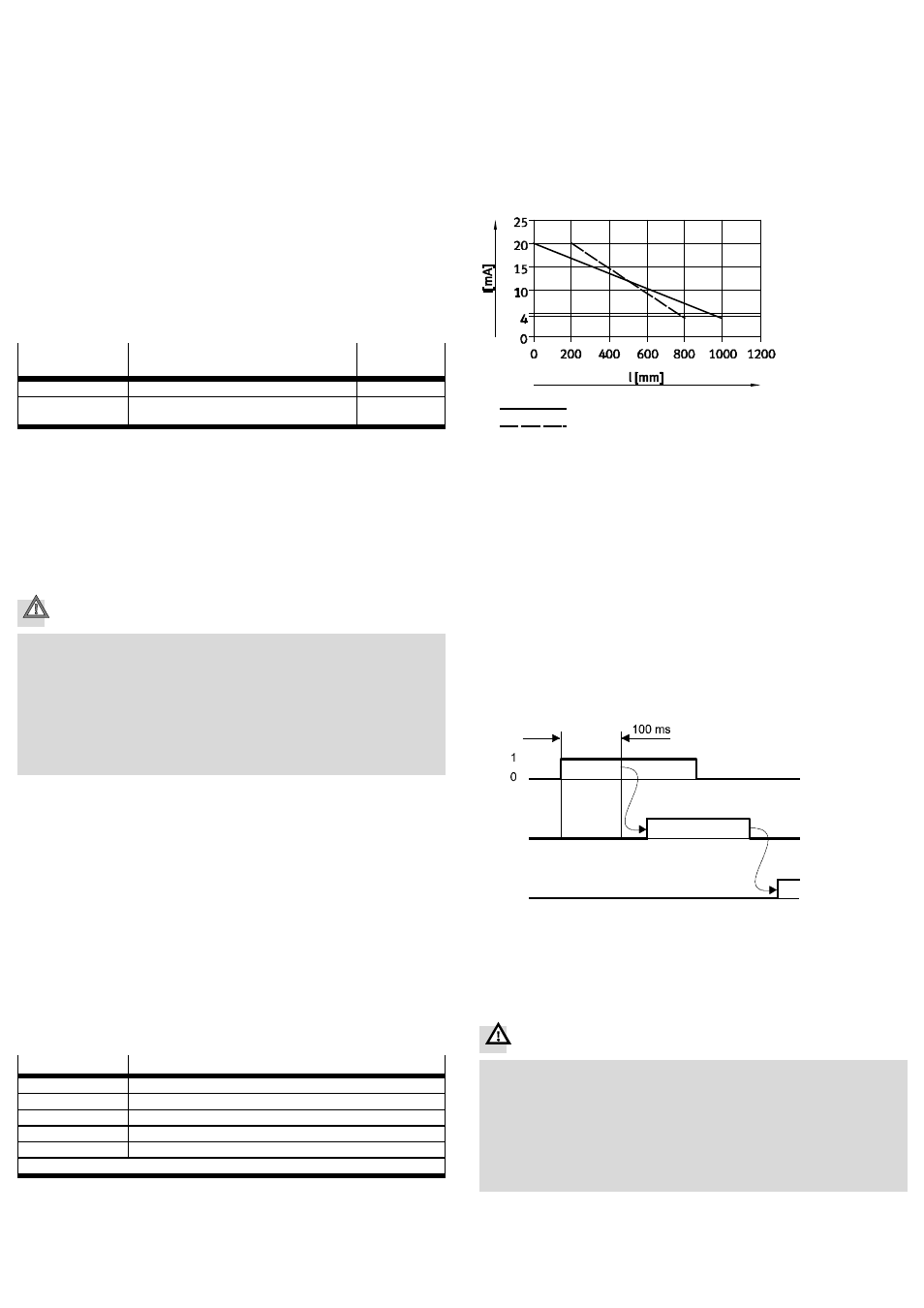
Example DFPI-...-990-...: Initialization of the stroke length l = 200 … 800 mm
Factory setting
Characteristic curve after initialization
End position 1 = 200 mm
End position 2 = 800 mm
Fig. 14 Characteristic curve shift (example)
During initialization the end positions of the DFPI are moved to automatically.
As a result, the positioner learns the available/used stroke length. After successful
initialization the linear drive is ready for operation. The integrated positioner now
ensures that the slide gate moves to the desired positions under closed-loop con-
trol – at the farthest to the end positions taught during the initialization.
Carry out initialization as follows:
1. Switch on the operating voltage supply and setpoint input. Otherwise the drive
will move to the safety position when the compressed air is switched on.
2. Switch on the compressed air supply. The drive moves to the specified setpoint
position.
3. Apply a logic 1 (+24 V) at pin 5 for t > 100 ms (see Fig. 15
1 ) – e.g. by briefly
bridging PIN 1 and PIN 5. The initialization process will then start (see Fig. 15
2 ).
Fig. 15
2
3
1
4. When the initialization is completed the DFPI is ready for operation
(
Fig. 15
3 ). It then travels to the specified setpoint position.
9
Operation
Warning
Uncontrolled fast moving parts can cause injury to people in the vicinity of the
DFPI.
• Make sure that, in the positioning range:
– nobody can place his/her hand in the path of moving components
(e.g. by providing a protective guard).
– there are no foreign objects in the path of the moving components.
It should not be possible to touch the DFPI until the mass has come to a com-
plete rest.