2 electrical installation, 3 pneumatic installation, For dfpi-...-...-nd2p-c1v-a – Festo Линейный привод с датчиком перемещения DFPI User Manual
Page 3
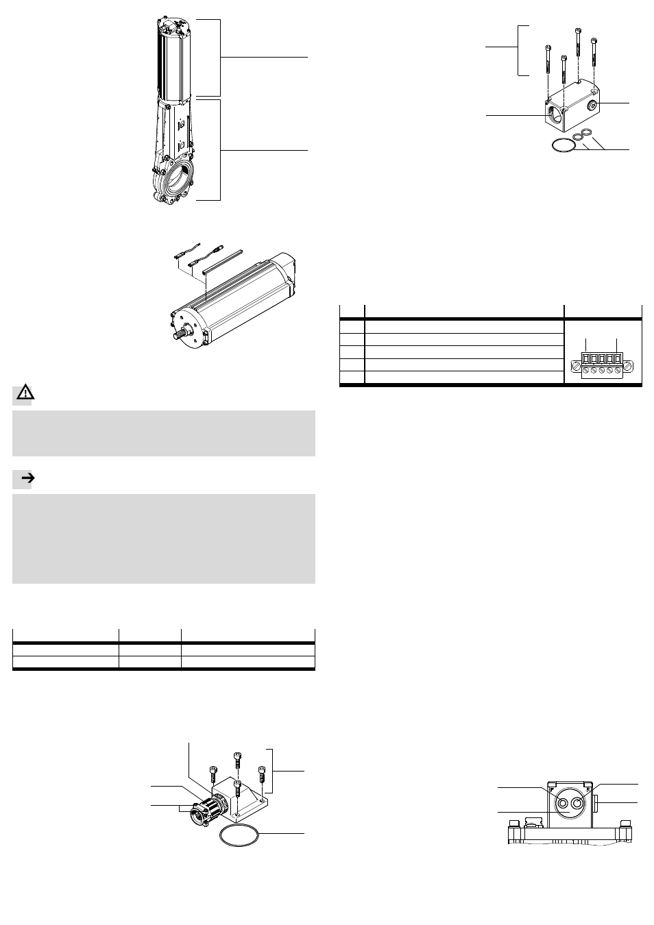
The adjacent illustration shows an
example of the mechanical
connection of a DFPI (
Fig. 5
1 )
to a process valve (
Fig. 5
2 ).
Observe the following during
installation:
• Mount the DFPI in such a way
that there are no lateral forces
acting on the piston rod bear-
ings.
• Mount the DFPI in such a way
that the required mode of opera-
tion for opening and closing the
process valve or penstock valve
is implemented.
Fig. 5
1
2
When using additional proximity
sensors:
• Place the proximity sensors in
the corresponding grooves. Cov-
er rails over the grooves fasten
the cables and protect them
against dirt.
• During assembly, maintain the
required minimum distances
from ferrous materials.
Fig. 6
7.2 Electrical installation
Warning
• Use only power sources which guarantee reliable electrical isolation of
the operating voltage in accordance with IEC/DIN EN 60204-1. Observe
also the general requirements for PELV power circuits in accordance with
IEC/DIN EN 60204-1.
Note
Installation errors can damage the electronics or cause malfunctions.
• Make sure that the length of the signal line does
not exceed the maximum
permissible length of 30 m.
• Connect the earth terminal (Fig. 1
9 ) to the earth potential with low imped-
ance (short cable with large cross-section) – tightening torque 5 Nm ± 10 %.
• Dimension pneumatic lines and electric cables sufficiently.
• Use an electric connecting cable, with at least 5 wires, with an outside dia-
meter of Fig. 7 – conductor cross-section [mm²]: 0.75 … 1.5.
• Recommendation: For the DFPI-...-C1V-P-A, use the pre-assembled connecting
cable NHSB with protective conduit according to accessories
(
www.festo.com/catalogue).
Type
Outside diameter [mm]
DFPI
-...-...-
C1V-A
Fig. 8
4.5
…
10
DFPI
-...-...-
C1V-
P-A
Fig. 9
6.5
…
8
Fig. 7
The electrical connection is concealed by the flange receptacle (
Fig. 1).
To perform electrical installation you will have to dismantle the flange receptacle.
For DFPI-...-...-ND2P-C1V-A
1 Mounting screws – tightening
torque 1.4 Nm ± 10 %
2 Seal
3 Tightening torque
0.3 Nm ± 10 %
4 Tightening torque
1.5 Nm ± 10 %
5 Tightening torque
3.5 Nm ± 10 %
Fig. 8
1
2
3
4
5
For DFPI-...-...-ND2P-C1V-P-A (protected pneumatic connections)
1 Mounting screws – tightening
torque 2.7 Nm ± 10 %
2 With guided air vent: plug
screw with sealing ring
(mounted at factory); With
on-site air vent: filter nipple or
silencer (accessories)
3 Seals (O-rings)
4 Mounting thread (M32 x 1.5)
for connection line
(accessories) – tightening
torque 15 Nm ± 10 %.
Fig. 9
1
2
3
4
1. Loosen the mounting screws of the flange receptacle (
Fig. 9
1 or Fig. 8 1 )
and carefully remove the flange receptacle.
2. For DFPI-C1V-A: If necessary, loosen the cable conduit fitting (
Fig. 8
3 ).
For DFPI-C1V-P-A:
Assembly instructions for connecting cable (accessories).
3. Route the electric cable through the flange receptacle.
4. If necessary, loosen the socket strip of the electrical connection, which is
fastened with two screws.
5. Use the wire end sleeves suitable for the connection and wire the socket strip
according to the pin allocation (
Fig. 10) – tightening torque 0.22 Nm …
0,25 Nm.
The integrated positioner is supplied with operating voltage and the setpoint sig-
nal via the following 5-pin plug connector.
Pin
Allocation
Connection
1
Power supply 24 V DC
1)
5
1
2
Input analogue setpoint value 4 … 20 mA
2)
3
GND Power supply/Input/Output
4
Output analogue actual value 4 … 20 mA
2)
5
Input initialisation 24 V DC
1)
Permissible operating voltage range
Technical data in section 13
2)
Reference between position and analogue value is dependent on the initialization (
Fig. 14)
Fig. 10
6. Carefully plug the wired-up socket strip onto the plug connector.
7. Fasten the socket strip with the two screws – tightening torque 0.5 Nm ± 10 %.
8. Mount the flange receptacle. When doing so, make sure that the seals are cor-
rectly seated – tightening torque
Fig. 8 or Fig. 9.
9. For
DFPI-...-...-ND2P-C1V-A:Retighten the cable conduit fitting – tightening
torque see Fig. 8.
For DFPI-...-...-ND2P-C1V-P-A before tightening the cable conduit fitting (accessor-
ies) you first have to perform the pneumatic installation (see section 7.3).
7.3 Pneumatic installation
• Check the necessity of an emergency compressed air supply and of non-return
valves. You will then avoid sudden compensating movements of the piston rod if
there is a drop in pressure and a sudden sliding down of the moving load in a
vertical or inclined mounting position.
• Connect the tubing of the DFPI as follows:
For DFPI-...-...-ND2P-C1V-A
1. If necessary, remove the adhesive labels from the supply ports.
2. Use only suitable threaded connectors – pneumatic connection G¼.
3. Connect the tubing of the DFPI to the compressed air connections (
Fig. 1).
– Connection P: compressed air supply port for operating pressure
– Connection R: exhaust port
For DFPI-...-...-ND2P-C1V-P-A (protected pneumatic connections)
• Use the pre-assembled connecting cable NHSB with protective conduit accord-
ing to accessories (
www.festo.com/catalogue) or externally calibrated pneu-
matic connection lines with the following outside diameter:
– Connection P: 8 mm; connection R: 10 mm
The flange receptacle has two threaded holes (
Fig. 11). Push-in fittings are
pre-assembled in the factory (included in scope of delivery).
1. If necessary, loosen the cable conduit fitting (
assembly instructions of the
accessories).
2. Remove the blanking plugs from the push-in fittings, if necessary.
1 Pneumatic connection P
2 Pneumatic connection R,
(guided exhaust)
3 From the plant: plug screw G¼
Optional – for on-site air vent:
filter nipple G¼ or silencer G¼
(accessories)
4 Passage for electric cables
Fig. 11
1
2
3
4