4 application, 5 transport and storage, 6 requirements for product use – Festo Линейный привод с датчиком перемещения DFPI User Manual
Page 2: 7 installation, 1 mechanical installation
The valve manifold controls the desired direction of movement by pressurising the
one cylinder chamber and simultaneously venting the other cylinder chamber with
or without flow control.
The current position is provided as an analogue current signal (4 … 20 mA) via the
actual value output and can be evaluated by a higher-order controller if needed.
The drive has a safety position set at the factory (
type code in Fig. 2). It re-
sponds as follows if the operating voltage supply or the analogue setpoint is out-
side the permitted range (e.g. in the event of a wire break):
For DFPI-...-...-C1V-A and ...-C1V-P-A:
– Piston rod is advanced (close process valve)
4
Application
The designated use of the DFPI linear drive is to drive linearly actuated, guided
process valves in process automation systems – for example guided gate valve
actuators and penstock valves. It is suitable for use in the process industry in the
area of:
– water, sewage, industrial process water,
– silage and bulk goods technology.
The stroke length of the drive is generally at least equal to the nominal diameter of
the process valves so that the gate valve actuator can be opened and closed com-
pletely using the DFPI.
The product is tailored to the requirements of process industries.
(
Catalogue www.festo.com/catalogue).
5
Transport and storage
Warning
Danger of crushing! Danger of shearing!
The DFPI can weigh up to about 86 kg, depending on the product version.
Body parts can be crushed or cut off if the product falls.
• For product versions weighing more than 12 kg, always use suitable
load-carrying equipment in order to handle the product safely during
transport and assembly.
Ensure storage conditions as follows:
– Short storage times, storage locations should be cool, dry and shady to prevent
corrosion.
6
Requirements for product use
Installation and commissioning are to be carried out only by qualified personnel in
accordance with the operating instructions.
Note
Lateral forces on the piston rod can damage the piston rod bearing of the DFPI.
• Make sure that there are no lateral forces acting on the piston rods, e.g.
through external guiding of the useful load (only guided process valves are
permissible).
Note
Continuous operation at the limits of the specified ambient temperature and
work frequency can reduce the service life of the drive.
• Use lubricated compressed air for continuous operation under extreme
conditions. The oil must be chemically inert (chemically resistant) and must
not carbonize.
Note
Improper handing can cause malfunctions or damage to the product.
• Make sure that all the instructions in this chapter are always observed.
The product will then function correctly and safely.
• Compare the maximum values specified in these operating instructions with
your actual application (e.g. pressures, forces, torques, masses, speeds, tem-
peratures). The product can only be used in accordance with the relevant safety
guidelines if the maximum load limits are observed.
• Ensure that all applicable national and local safety laws are adhered to.
• Take into consideration the ambient conditions at the location of use. Corrosive
environments reduce the service life of the product.
• Remove the packaging except for the adhesive labels on the compressed air sup-
ply ports (danger of contamination). The material used in the packaging has been
specifically chosen for its recyclability (exception: oil paper = residual waste).
• Use the product in its original status, without any unauthorised product modific-
ations.
•
Do not loosen or remove the pressure compensation element. This can damage
the product.
• Protect the device from fluctuations in pressure and excess operating
temperature. Use excess pressure and pressure regulating valves.
• Make sure there is a supply of correctly prepared compressed air –
(
Technical data chapter 13).
• Use only non-lubricated compressed air under normal conditions. The product
has an initial lubrication which suffices for the complete service life. Using lub-
ricated compressed air flushes out the initial lubrication. The product may then
only be operated with lubricated compressed air.
• Make sure that cut-off tube ends are cut off square and are free of burrs. This
way you prevent damage to internal O-rings of the DFPI when the compressed
air tubes are inserted.
• Please select the corresponding accessories, e.g. connecting cables and proxim-
ity sensors, from our catalogue (
www.festo.com/catalogue).
• Use only proximity sensors approved for the product from out catalogue
(
www.festo.com/catalogue).
• Always perform an initialization of the drive in the following cases (
section 8):
– After installation on initial start-up
– After resetting of the flow control valves
– After changing the operating pressure
– After changing the process that influence the forces, e.g. at the slide gate,
and thus the process parameters
– After changing the stroke length used (stroke modification).
Initialization teaches the positioner the available/used stroke length and vari-
ous system characteristic values. The taught values are retained if there is a
failure of the power supply.
7
Installation
Note
When proximity sensors are used: Ferrous materials (e.g. steel parts and metal
sheets) in the immediate vicinity of proximity sensors can result in undesired
switching signals. When linear drives are installed too close to each other, a
cylinder magnet can trigger switching of the proximity sensor on the adjacent
linear drive.
• During assembly, maintain the required minimum distances from ferrous ma-
terials. The required distances must be determined during assembly for each
specific case!
• When installing more than one linear drive, make sure that the effective area
of each cylinder magnet does not impact any proximity sensors of adjacent
linear drives.
If there are high medium temperatures in the tubing and the process valve:
• Use a heat-insulated coupling extension.
7.1 Mechanical installation
For attachment, the linear drive has a mounting hole pattern in accordance with
DIN 3358. Through this, the linear drive is screwed to the process valve or
penstock valve. The mounting orientation is any desired.
• If necessary, use the corresponding adapters for attachment
(
catalogue www.festo.com/catalogue).
• Attach the DFPI with 4 screws.
• Tighten the mounting screws evenly. Tightening torques: with M8 thread
25 Nm ± 5 %; with M10 thread 46 Nm ± 5 %.
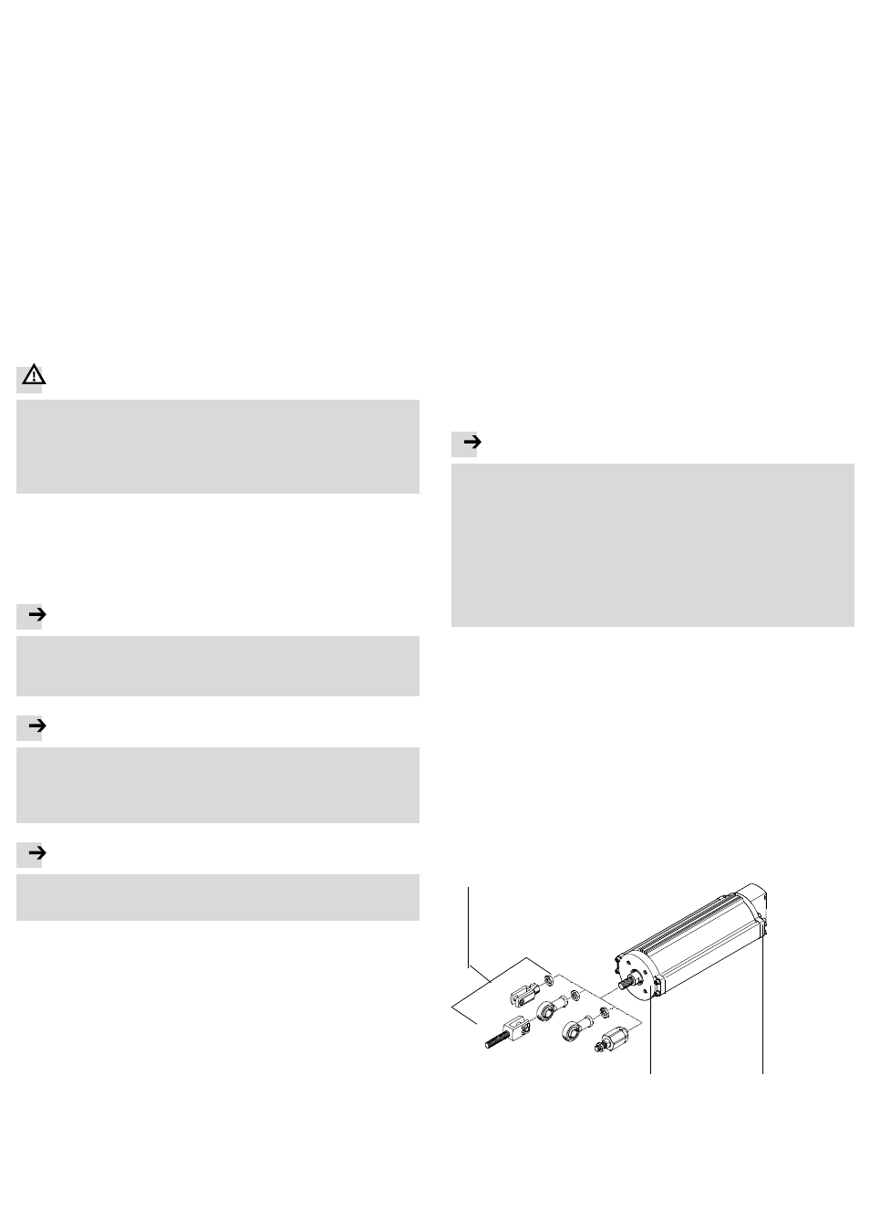
The piston rod has a male thread for mounting the slide gate.
The spanner flat at the piston rod is used as a counter holder to avoid impermiss-
ible torques at the piston rod – width across flats
technical data in chapter 13.
• If necessary, use the corresponding adapters for attachment
(
catalogue www.festo.com/catalogue).
Fig. 4
2
1
3
1 Adapter for attachment of the
slide gate – examples
2 End cap
3 Bearing cap with mounting thread
(4) for installation – hole pattern in
accordance with DIN 3358