Voicebox 4 i/op user manual, 1 – hardware connections, 1 – input from an unbalanced source – Attero Tech Box 4 I/OP User Manual
Page 9
VoiceBox 4 I/OP
User Manual
Attero Tech LLC 2010
Page 5
614-00008-02
Installation of the VoiceBox is very straight forward. All connections to the VoiceBox should be made before the power is
applied.
o
Attach any audio sources that will be used to the inputs. The inputs are balanced so be sure to check what output
type the source is in order to find how to connect it correctly (see section 2.1 – Hardware Connections).
o
Select phantom power and/or the level of input gain required as necessary.
o
Attach the outputs to the required audio devices. The outputs are balanced so be sure to check what input type
the device requires in order to find how to connect it correctly (see section 2.1 – Hardware Connections).
When powering using PoE:
o
Attach the CobraNet I/F port to a spare PoE-enabled port on a PoE switch using a CAT-5 cable. If a midspan
injector is being used, connect a spare input port to the CobraNet network switch using a CAT-5 able, and then
connect the corresponding output port to the CobraNet I/F of the VoiceBox.
When powering using an optional external supply:
o
Attach the CobraNet I/F port to a spare port on the CobraNet network switch using a CAT-5 cable.
o
Attach the power supply to the power input jack and then power up the external supply.
If all steps are performed correctly, the power light on the front should be lit.
There may also be some activity on the VoiceBox CobraNet I/F LED indicators. With no CobraNet network, the LED on the
right of the CobraNet I/F port will be on. If another active CobraNet device is detected on the network or the Attero Tech
Control Center application or other similar CobraNet application program is active on the network, the left hand LED will be
flashing at a rate around three times per second and the right hand LED may either also flash or remain steady.
2.1 – Hardware Connections
The VoiceBox 4 I/OP accepts and drives either unbalanced or balanced audio devices. Refer to the following diagrams and
instructions for connecting different types of audio devices. Professional grade audio cabling is recommended to achieve
the best audio performance throughout the system.
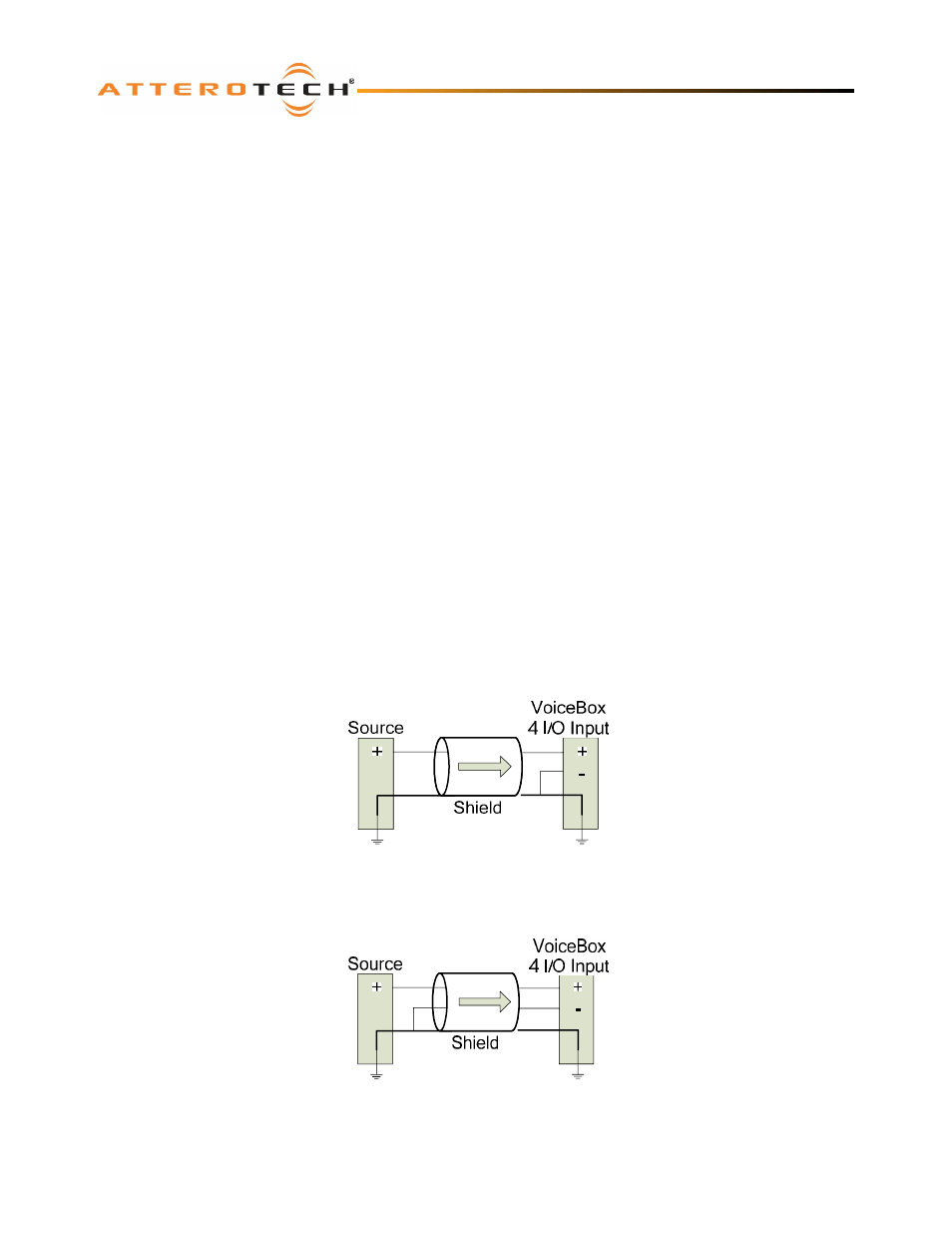
2.1.1 – Input from an Unbalanced Source
To connect a 2-wire unbalanced source to the VoiceBox 4 I/OP, connect the positive output of the unbalanced source to the
positive input of the VoiceBox 4 I/OP. Connect both the source and VoiceBox 4 I/OP input grounds together, and short the
negative input of the VoiceBox 4 I/OP to round at the input of the VoiceBox 4 I/OP.
Figure 4 - 2-Wire Unbalanced Source Connection
To connect unbalanced sources with a 3-wire connection, short the negative conductor to the shield at the source
connection.
Figure 5 - 3-Wire Unbalanced Source Connection