Voicebox 4 i/op user manual, 1 – input eq, 2 – input compressor – Attero Tech Box 4 I/OP User Manual
Page 14: 3 – input gain
VoiceBox 4 I/OP
User Manual
Attero Tech LLC 2010
Page 10
614-00008-02
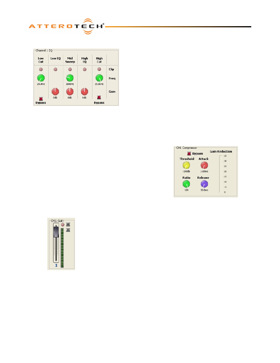
3.2.1 – Input EQ
The input EQ consists of several cascaded filters: a low and high cut,
a low EQ, a mid sweep and a High EQ.
The low cut is a 12dB / Octave filter with adjustable frequency. The
high cut is a 6dB / Octave filter with adjustable frequency. The low
EQ is a low shelf filter set at 400 Hz with adjustable gain. The mid
sweep is a parametric EQ with a fixed bandwidth of 1 Octave but
adjustable frequency and gain. The high EQ is a high shelf filter set
at 3 kHz with adjustable gain.
In each case the frequency can be adjusted from 20 Hz to 20 kHz
and the gain controls work from -12 dB to +12 dB. The high cut and
low cut filters also have a bypass facility which, when active, will
cause that filter to be bypassed and have no affect on the audio
signal.
Each stage also has a clipping LED which lights red when clipping
occurs.
3.2.2 – Input Compressor
The Input Compressor consists of four controls, a Bypass button, and a
Gain Reduction meter.
The Bypass button allows the compressor to be completely bypassed and
its settings ignored. Click on the button to toggle the state of the
bypass. If the red indicator is on, the bypass is activated.
The Threshold value ranges from -100 dB to 0 dB. The Ratio value ranges
from 1:1 to 100:1. The Attack value ranges from 1ms to 1s and the
Release value ranges from 10 ms to 30 s.
If any compression takes place, the Gain Reduction meter will show the
amount of signal attenuation.
3.2.3 – Input Gain
The Input Gain control allows the overall level of the signal to be adjusted before it is
fed into the mixer.
The fader sets the gain from -100 dB to +12 dB. The meter alongside shows the
current level after all the input processing has taken place, including the gain factor.
There is also a clipping LED.
The gain control also has two toggle indicators. The upper one marked with an “M” is
the “Mute” button. The lower button marked with an “I” is the “Polarity Invert” button.
Figure 13 - Input Compressor Controls
Figure 14 - Input Gain Controls
Figure 12 - Input EQ Controls