Voicebox 4 i/op user manual, 2 – input processing – Attero Tech Box 4 I/OP User Manual
Page 13
VoiceBox 4 I/OP
User Manual
Attero Tech LLC 2010
Page 9
614-00008-02
3.2 – Input Processing
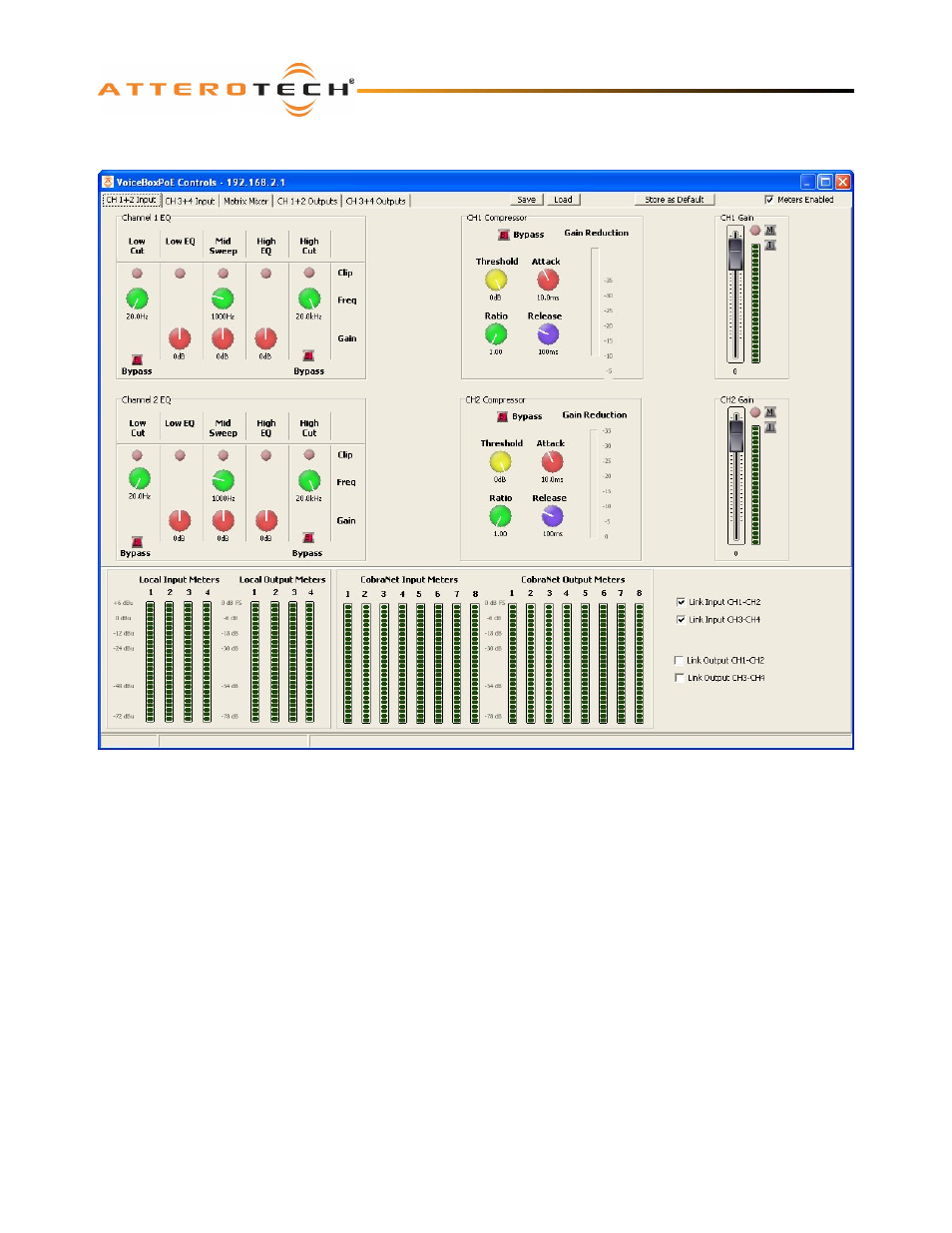
Figure 11 – Local Input Channel Processing for Channels 1 and 2
Figure 11 shows the general layout of the form. It contains five tabs. The first two tabs are dedicated to local input
processing with two input channels on each tab. The third is dedicated to the Matrix Mixer. The final two tabs are
dedicated to local output processing with two output channels on each tab.
For controls that utilize either a control knob or a fader, the value can be altered by clicking and holding the left mouse
button down on the control and dragging the mouse forward or backward to alter the value upward or downward
respectively.
The value can also be typed in if the controls have their value shown underneath. Clicking on the control will highlight the
complete text and typing a new value will overwrite the current text. The controls accept shorthand notation such as 10k
for 10000 and 10m for 0.01. They will also accept the correct unit if entered, though it is not necessary to include it. Once
the required value is entered, press the Enter key to complete the process and accept the new value. If a valid number is
entered, the control will change to the newly entered number or as close to it as the control’s range allows. The control will
revert back to its previous value if an invalid number is entered.
Notes:
o
If the Enter key is not pressed after entering a new value and a different control is selected, the control that was
being edited will revert to its previous value.
o
When a fader or knob control value is changed, its value is sent to the device only once the Enter key is pressed or
the mouse is released.
The other type of control is an indicator button. These are either grey for off or colored (red, green, or yellow) for on. To
change the state of the button from on to off or from off to on, left-click on it.