Inbox / outbox user manual, 2 – inbox controls – Attero Tech InBox/OutBox User Manual
Page 15
InBox / OutBox
User Manual
Attero Tech LLC 2010
Page 10
614-00005-04
4.2 – InBox Controls
The following section describes the operation and controls available for the following devices
o
InBox X2 - V1.0.2.563
o
InBox R8 - V1.0.2.581
o
InBox M3 - V1.0.2.44
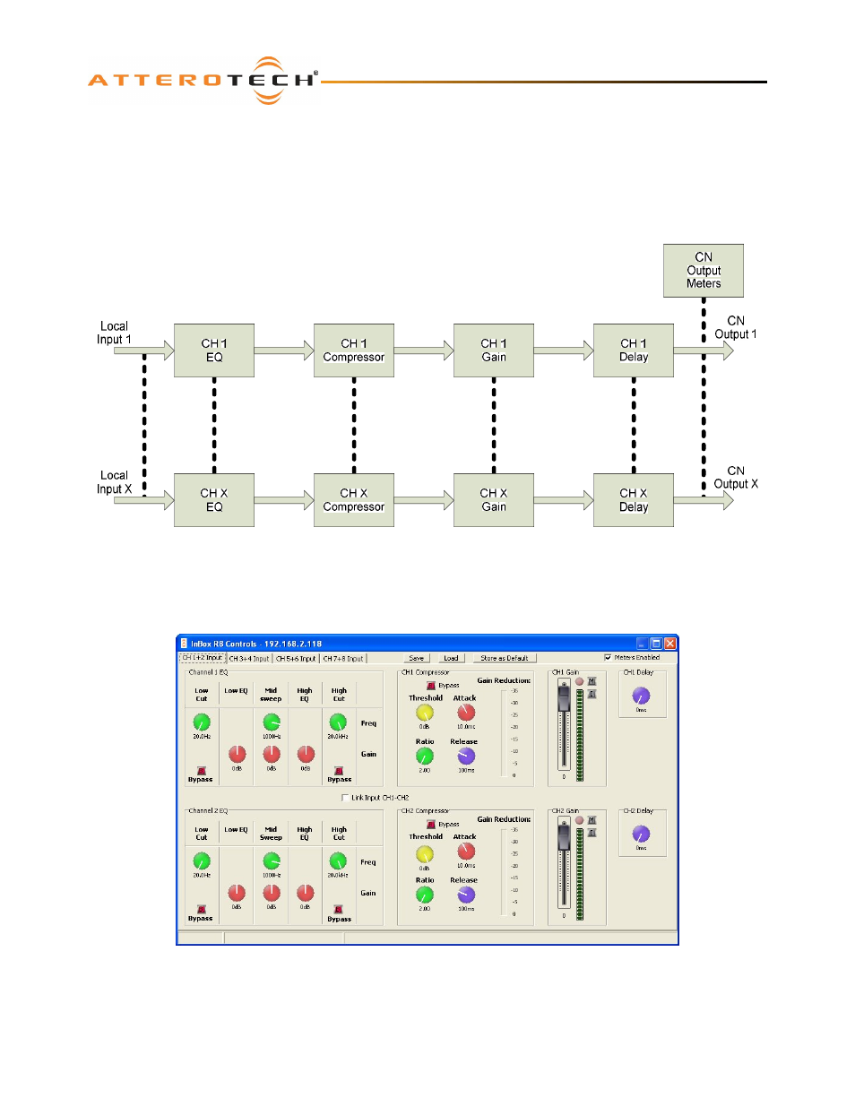
The audio path in an InBox is shown in Figure 8 with each input has its own unique set of controls.
Figure 8 – InBox DSP Architecture
The audio from the local input is fed through an EQ stage, a Compressor stage, a Gain stage, and finally, a delay stage. The
processed signals are then available to be routed over the CobraNet network. Any unused CobraNet output channels are
filled with audio from incoming CobraNet bundles to allow for bundle blending (see section 3 for details).
Figure 9 – Control Form for InBox R8
The typical interface for an InBox is shown in Figure 9 and although the screenshot is for the InBox R8, both the Inbox M3
and InBox X2 have identical controls except the InBox M3 only has 3 tabs (CH1-XLR, CH 2+3-RCA, and CH4+5-Stereo jack)
and the InBox X2 has no tabs as all controls are on the one page.