Half- stepping current wave form – RMS Technologies IMC17 INTEGRATED MOTOR CONTROLLER/DRIVER User Manual
Page 22
Old 4-Pin cable
Connect
to
New 3-Pin cable
Pin #
Color/function
Color/function
Pin #
Pin 1
Red (PWR)
No connection
--
Pin 2
Green (GND)
Green (GND)
Pin 2
Pin 3
Brown RS485 B (+)
Brown RS485 B (+)
Pin 3
Pin 4
Black/white RS485 A (-)
Black/white RS485 A (-) Pin 1
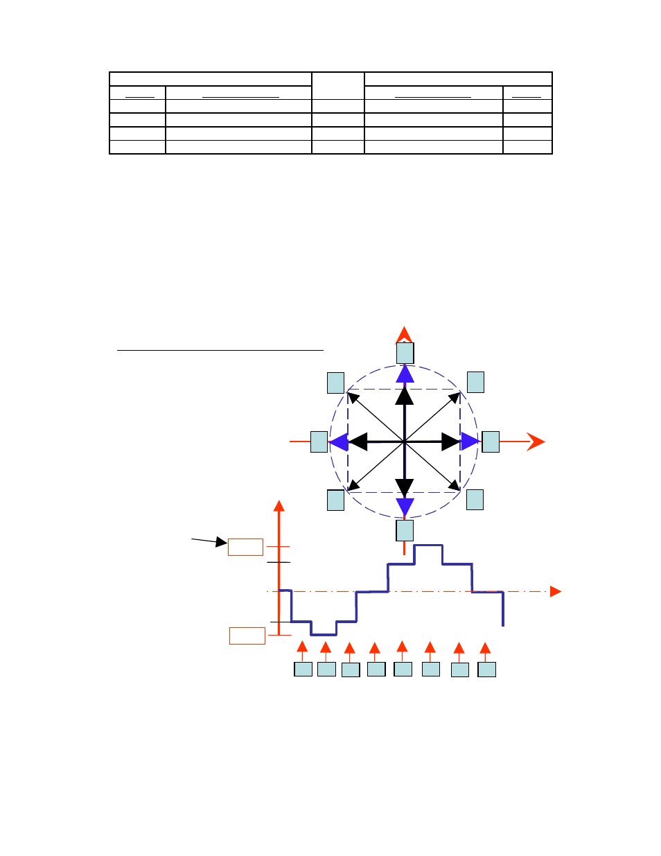
Peak current versus Amps/Phase
Where does the 1.4 times come from? Current is continuously changing when a
motor steps. If the motor is rated for 1.0 A/Ph, it may receive 0 Amps, 1 Amp, 1.4
Amps, or anything in between if you are microstepping. For ease of explanation, we
will look at the current waveform when we half step, or set the driver/controller to 2x
microstepping.
If we take a look at both the A and B phases, and plot on an X-Y chart of when each
phase receives current, and how much it receives, it will look like the chart below.
Beginning at position 1, Phase A receives negative current, and Phase B receives
positive current. Let’s assume it is at coordinate (-1, 1).
The position versus time graph just above, plots only the A Phase, following the eight
different steps the motor will make. Current is changing with each position. Recall
that a negative in electronics simply means reverse direction of current flow.
RMS Technologies
Page 22
4/3/2009
IMC17/IMCE17 User Manual
Rev 1.06
1
3
7
5
1
2
3
4
100%
100%
0%
HALF- STEPPING
Current Wave Form
PHASE A
Current
POSITION
PHASE B
PHASE A
2
4
8
6
5
6
7
8
141%
141%
time
Peak current
(1.4 times Amps/Ph)
Average, or RMS
Is only 1 Amp/Ph