RMS Technologies IMC17 INTEGRATED MOTOR CONTROLLER/DRIVER User Manual
Page 11
(Figure 5)
1.
The USB converter card connects to the IMC17 using the DB-9 cable that is
provided to you. The 3-Pin connector is placed onto the converter card.
2.
Your power supply will be connected to the IMC17 directly. The USB card is
powered via the PC. IMC17’s pin1, Red wire is +12-40VDC, pin 6, Green
wire is Ground.
3.
Connect the USB card to your PC using the USB cable provided to you. You
will need to download driver files (2 of them). You can find them at:
4. Turn your power supply on and follow instructions for using HyperTerminal.
Mating Connectors
ADB-9 cable is provided
with every motor. The
opposite end has flying
leads and a 3-pin
connector for RS485
communication.
7. CONFIGURING AND CONTROLLING THE IMC17
HyperTerminal Setup
Please follow these steps in order to properly set up HyperTerminal:
1.
Open a terminal from your PC by following these steps: Start Menu Programs
Accessories Communications HyperTerminal
2. Assign a name for your New
Connection
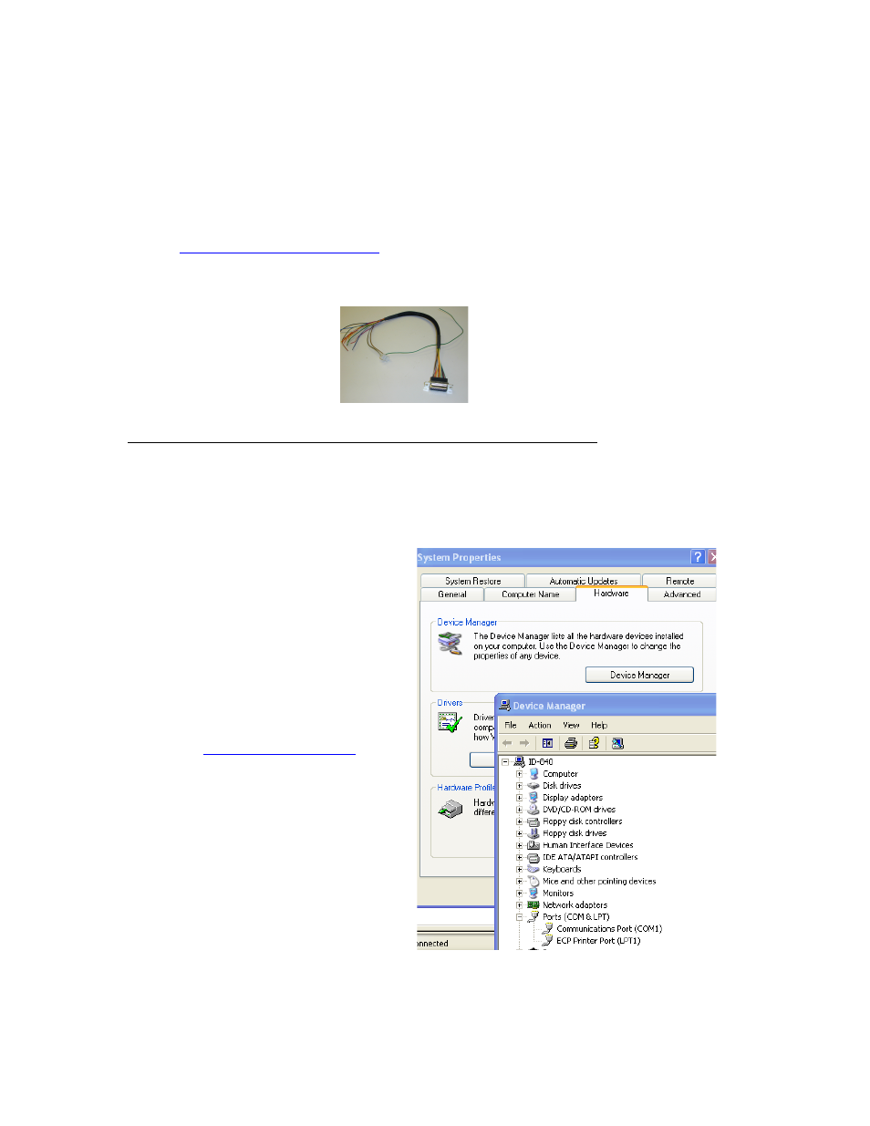
3. Determine the correct COM port # by
right clicking on “My Computer” and
selecting “Properties”. Select the
“Hardware Tab” and click on “Device
Manager”.
Note: if you are using the USB485
converter card, first download driver files
(found online:
.
You should then see the RMS USB 485
converter card in the “Ports (COM & LPT)”
area.
If you are connecting via RS232, most
likely it is COM1, “Communications Port”.
RMS Technologies
Page 11
4/3/2009
IMC17/IMCE17 User Manual
Rev 1.06