RMS Technologies IMC17 INTEGRATED MOTOR CONTROLLER/DRIVER User Manual
Page 17
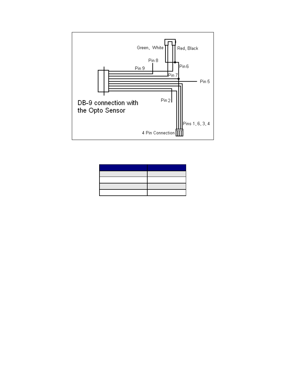
Optical Sensor
Figure 10: Opto Sensor Connection Schematic
The Opto Sensor uses Pins 6, 7, and 9. Use the following table to solder the
corresponding wires.
Optical Sensor
DB9 Cable
Green
Green
Black
Green
Red
Yellow
White
White
Table 8
Use the Z command and state the max number of steps you want it to search for
home. The unit will either stop at the opto sensor or when it finishes moving your
designated number of steps. For example:
/1Z500000R
Motor will take 500,000 steps and stop OR Motor will stop once the optical sensor
has been interrupted. Only input #3 can work with the optical sensor. The LED
output on pin 9 can output a max of 20mAmps (200 ohms internal resistor and 5VDC
output)
RMS Technologies
Page 17
4/3/2009
IMC17/IMCE17 User Manual
Rev 1.06