Bell & Gossett P2001406C Series e-1510 Centrifugal Pumps User Manual
Page 20
Align a standard sleeve type coupling (black rubber sleeve)
WARNING:
Always disconnect and lock out power to the driver before you perform any installation or
maintenance tasks. Failure to disconnect and lock out driver power will result in serious
physical injury.
NOTICE:
• Do not rotate the coupler to make adjustments. This may result in equipment
damage.
• Do not move or shim the driver unless you need to make adjustments. This may result
in decreased performance.
Make sure you have the following before you start this procedure:
• A micrometer or a caliper
• A maximum 1/64 in. (0.397 mm) end clearance between the sleeve and the two
coupling halves
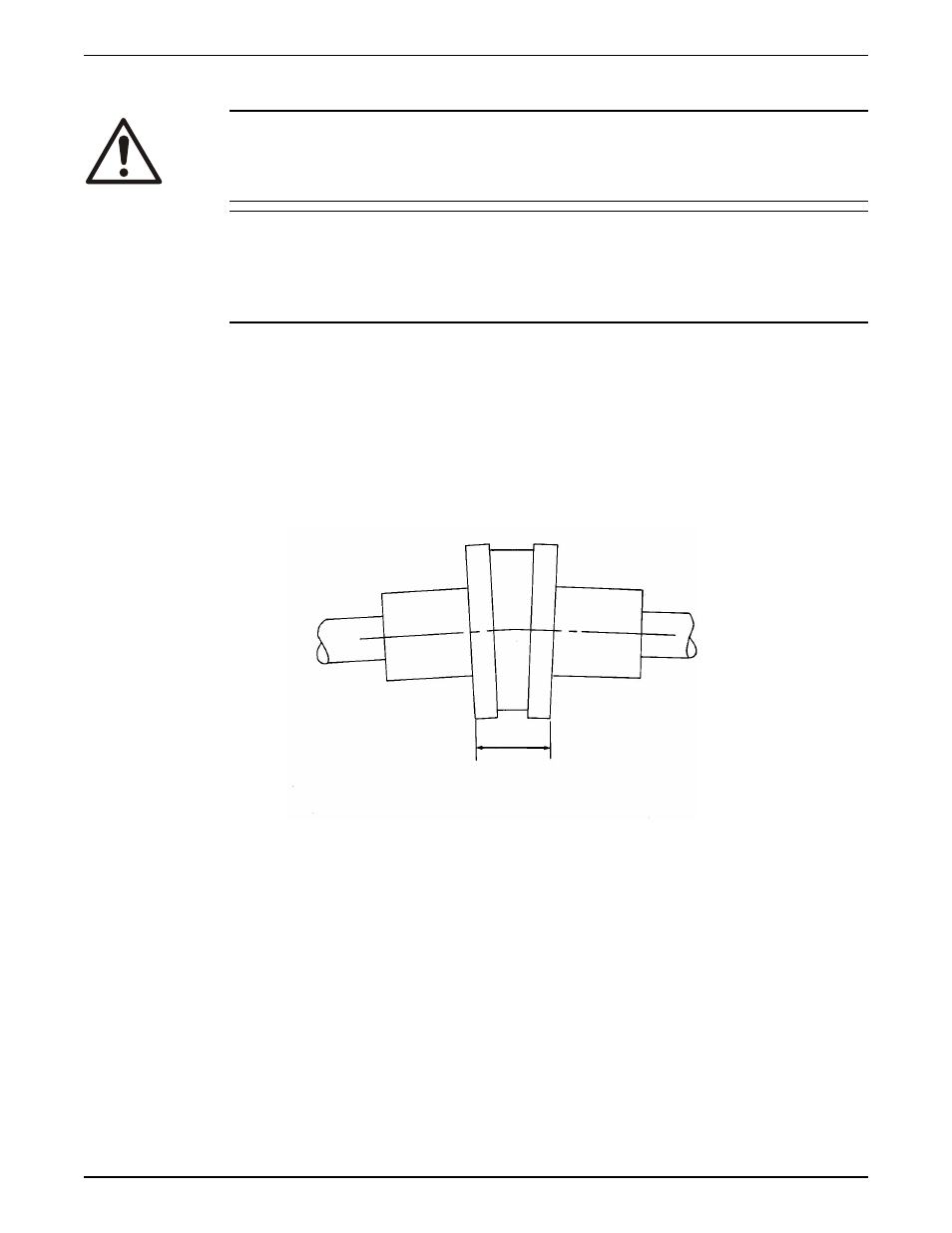
1. Check for angular misalignment:
a) Measure from the outside face of one flange to the outside face of the opposite
flange at four points 90° apart. Use the micrometer or the caliper.
The maximum permitted mis-alignment value is 1/64 in. (0.397 mm) per inch of
the coupling hub radius.
1
1.
Distances Across Coupling Flanges Should Be Equal (check 4 places)
Figure 3: Example of angular misalignment
b) Move or shim the drive unit, if necessary, until the permitted reading value is
obtained.
2. Check for parallel misalignment:
a) Put a straight edge across one coupling half.
b) Measure the gap between the straight edge and the opposite coupling half. Use
the micrometer or the caliper.
A gap of maximum 1/64 in. (0.397 mm) is permitted.
Installation
18
Series e-1510 Installation, Operation, and Maintenance Manual