Pump station with npe pumps – Bell & Gossett 10 001 247 R3 TechnoForce Package System User Manual
Page 29
Seventh character: Stages / impeller size
1 = 1, 2 = 2, 3 = 3, and so forth
Eighth character: reduced number of stages
0 = 0 reduced, 1 = 1 reduced, 2 = 2 reduced, and so forth
Ninth character: Branch
A = 1.5 in. Chk
D = 3 in. Chk
G = 1.5 in. PRV
K = 3 in. PRV
B = 2 in. Chk
E = 4 in. Chk
H = 2 in. PRV
L = 4 in. PRV
C = 2.5 in. Chk
F = 6 in. Chk
J = 2.5 in. PRV
M = 6 in. PRV
Tenth character
For factory use
Eleventh character: Options
B = Suction pressure switch
G = Suction pressure sensor
J = LOP
C = High temperature relief valve
D = System flex connectors
F = Lightning arrestor
Special options for B, G, J
Constant
Variable
Lift/flooded
LOP (option J)
Boost (greater than 10 PSI)
Switch (option B)
Switch (option B or G)
Pump station with NPE pumps
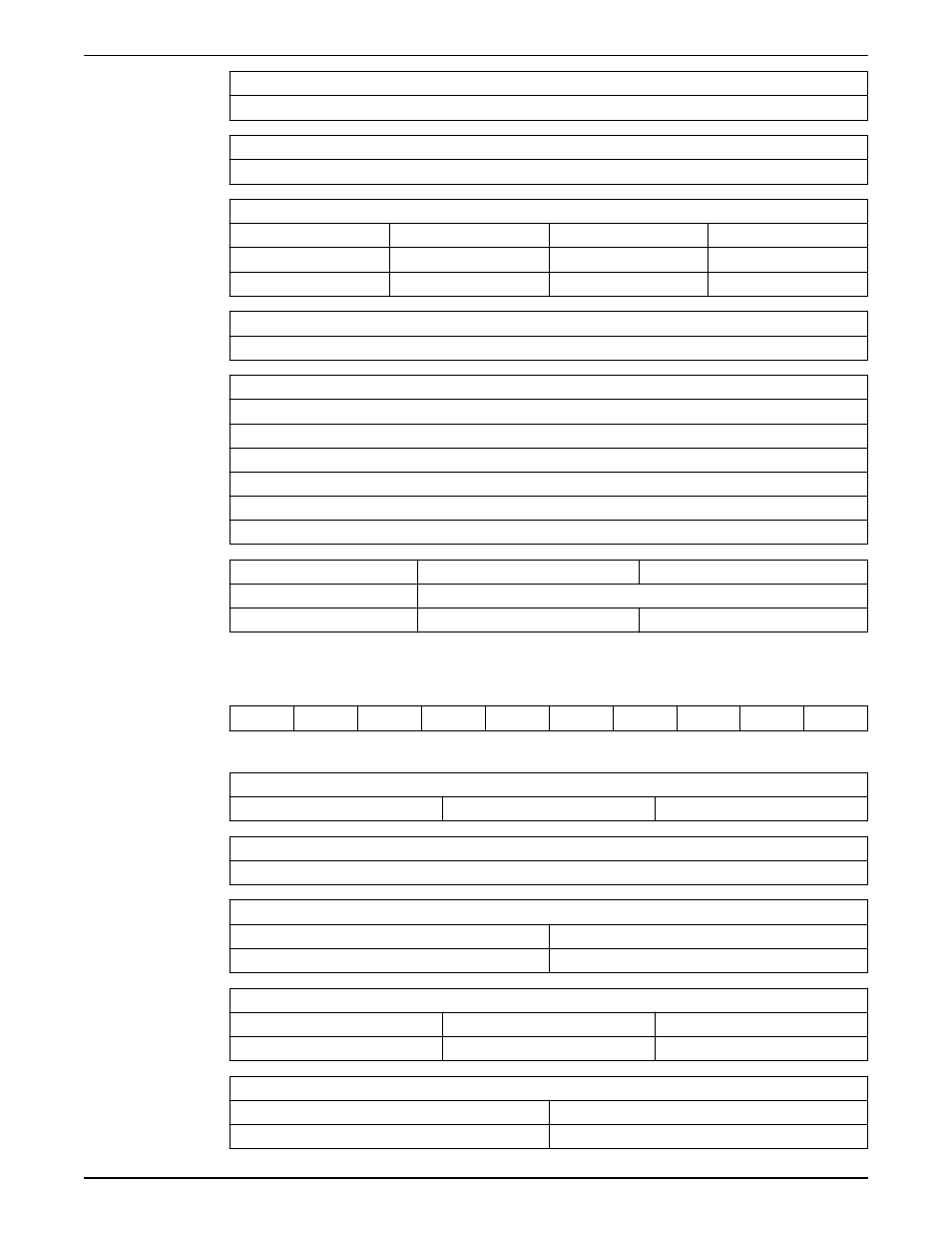
Example product code
C
2
N2
C
2
A
B
G
2
BCD
Numbering system definitions
First character: Variable or constant speed
V = variable speed
X = XLS variable speed
C = constant speed
Second character: Number of pumps
2, 3, or 4
Third character: Pump type and size
N1 = 1ST
N3 = 3ST
N2 = 2ST
Fourth character: Header size
C = 3 in.
E = 6 in.
G = 10 in.
D = 4 in.
F = 8 in.
H = 12 in.
Fifth character: Supply voltage
2 = 208 V / 1 PH / 60 Hz
6 = 460 V / 3 PH / 60 Hz
3 = 230 V / 1 PH / 60 Hz
7 = 575 V / 3 PH / 60 Hz
Technical Reference
TechnoForce and TechnoForce XLS Package System Mechanical Installation, Operation, and Maintenance
Manual
27