Goulds Pumps 3311 - IOM User Manual
Page 10
10
3.1.5 Minimum flow line
The minimum flow line (or bypass line) should be used if
operation with the discharge side shut-off valve closed is
possible. The minimum flow valve ensures that a
sufficient rate is automatically returned to the suction side
tank.
The minimum flow rate is shown on the curves or the data
sheet.
Size
t = 140 °C or lower
t > 140 °C
2x3-7
20 % of Q
BEP
25 % of Q
BEP
2.5x4-8
20 % of Q
BEP
25 % of Q
BEP
4x5-11
25 % of Q
BEP
25 % of Q
BEP
Should exact calculation be required, please contact
Gould’s Pumps.
CAUTION
• Up to the shut-off or non-return valve, the line should
be designed to suit the nominal pressure of the
discharge line, afterwards in accordance with the
design pressure of the feedwater/suction tank.
• Permissible velocity in the minimum flow line: 7 to 10
m/s.
• If an automatic device (bypass non-return valve) is
used, ensure that even in the case of trouble, liquid can
be returned through the minimum flow line.
• Frequent checks are recommended. Early replacement
of the minimum flow valve (which is exposed to
heavy wear) will prevent energy losses.
• The minimum flow valve should be installed near the
pump discharge nozzle, upstream from the discharge
shut-off valve.
• A non-return valve should be installed in the
minimum flow nozzle or the minimum flow line.
• For repair or overhaul work on the pump or the bypass
non-return valve, a shut-off valve must be installed in
the minimum flow line (c).
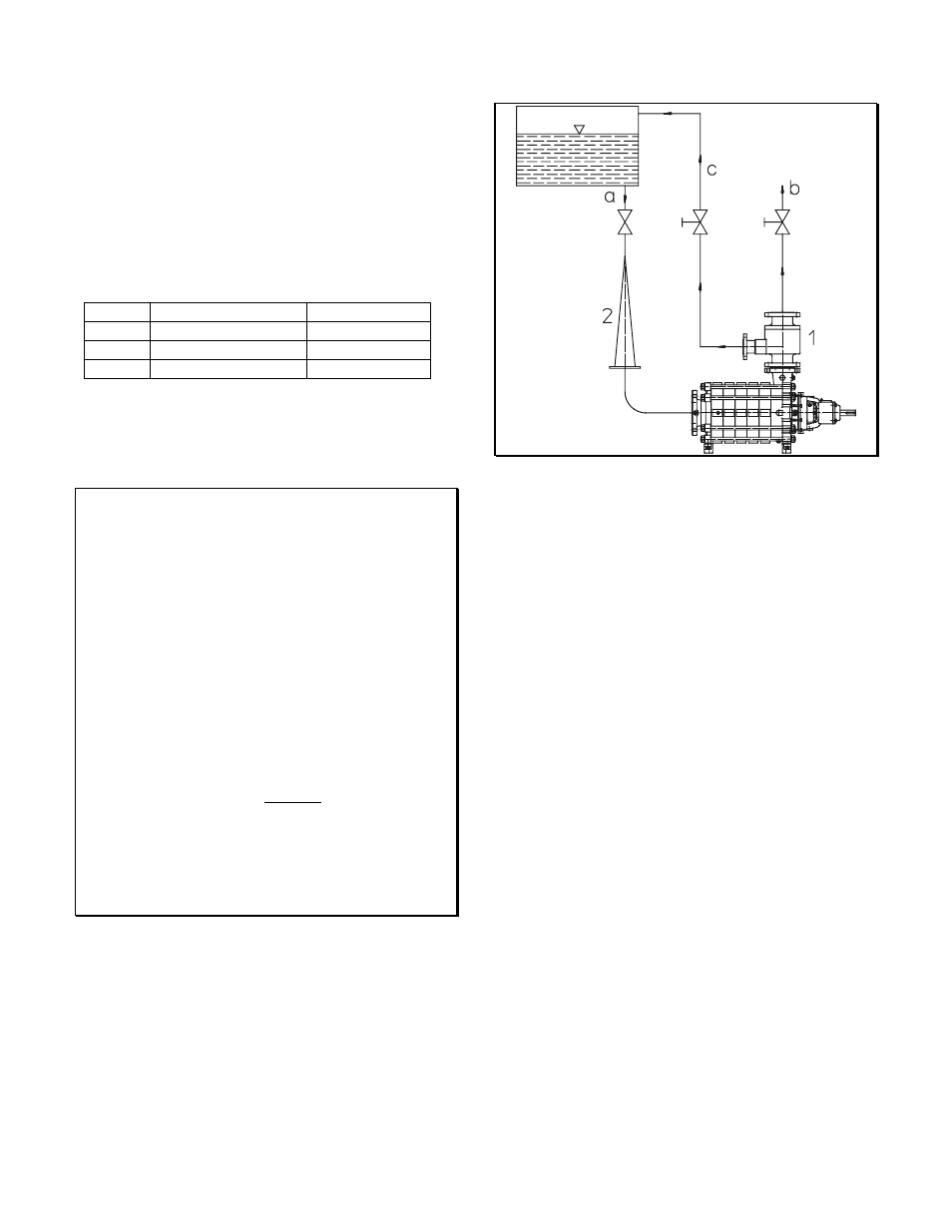
a Feed line
b Discharge line
c Bypass line
1 Bypass non-return valve
2 Conical strainer
Minimum flow control
3.1.6 Balancing line
The balancing line connects the discharge side shaft
sealing casing with the suction casing. There is no
throttling or shut-off device in this line, which serves to
hydraulically balance the pump.
The balancing line can also be returned by the customer to
the feed tank or the feed line.
3.1.7 Venting during pump priming
Before starting the set, the pump and the suction line must
be completely vented and filled with the liquid handled.
To bleed the air, several holes with plugs have been
provided. Similar holes may be used in the pipework. The
shut-off valve in the suction or supply line must be fully
open.