Minka Group F707-FLP User Manual
Page 13
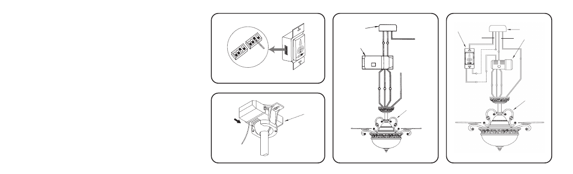
Fig.13
Fig.12
Fig.14
Fig.15
RECEIVER
OUT LET
BOX
RECEIVER
FAN
RECEIVER
OUTLET BOX
WALL CONTROL
GROUND
GREE
N
BLACK
BLACK
BLACK
BLACK
BLACK
BLACK
WHITE
WHITE
BLUE
BLUE
BLACK
WHITE
Step 4.If your outlet box has a GROUND wire (Green
or Bare Copper) connect this wire to the Hanger Ball
and Hanger Bracket Ground wires. If your outlet box
does not have a Ground Wire, then connect the Hanger
Ball and Hanger Bracket Ground Wires together. Secure
wire connection with the plastic wire nut provided.
(Fig. 14 & 15)
After all splices are made, check to make sure there
are no loose strands. As an additional precaution w
suggest to secure the plastic wire
connectors to the wires with electrical tape.
Note: Fan must be installed from a maximum distance
of 40 feet from the transmitting unit for proper signal
transmission between the transmitting unit and the
fan's receiving unit.
- F689-PW (24 pages)
- F582-ORB (26 pages)
- F539-BCW (24 pages)
- F518-WH (22 pages)
- F705-STW (9 pages)
- F620-BCW (27 pages)
- F402-ORB (25 pages)
- F513-BN (24 pages)
- F614-DBB (23 pages)
- F823-DK (24 pages)
- F695-KA (23 pages)
- F701-DRB (15 pages)
- F547-BS/DW (15 pages)
- F572-WH (9 pages)
- F566-WH (12 pages)
- F753-BNW (24 pages)
- F510-BS (24 pages)
- F522-WH (26 pages)
- F581-BG (14 pages)
- F659-PBL (24 pages)
- F889-ORB (26 pages)
- F733-BK/RW (24 pages)
- F696-KA (24 pages)
- F565-WH (13 pages)
- F734-SI (25 pages)
- F514-BN (30 pages)
- F594-WH (23 pages)
- F603-BN (15 pages)
- F711-PW (23 pages)
- F888-ORB (26 pages)
- F544-GBZ (22 pages)
- F521-ORB (26 pages)
- F548-WH (24 pages)
- F803-LN (27 pages)
- F637-ORB (22 pages)
- F647-SWH (23 pages)
- F563-SP-BS/DW (23 pages)
- F588-SP-BN (25 pages)
- F524-ABD (22 pages)
- F571-DRF (22 pages)
- F302-BN (23 pages)
- F602-BN/CH (26 pages)
- F833-SL (22 pages)
- F853-BN/MM (24 pages)