Model 1009 • dmx/rdm splitter manual, Esta, Specifications – Pathway #1009 DMX/RDM Splitter User Manual
Page 2: E1.20 remote device management, Dmx termination, Rdm enable/disable rdm responder features, Dmx thru connector, Typical system layout
rev.1 v1
3/09
Printed in Canada
www.pathwayconnect.com
Pathway Connectivity Inc
103-1439 17Avenue SE Calgary AB Canada T2G 1J9
tel (403) 243-8110 fax (403) 287-1281
ESTA
E
NTERTAINMENT
S
ERVICES
&
T
ECHNOLOGY
A
SSOCIATION
P
OWER
S
UPPLY
:
9-30 VDC, 6W
I
NPUT
S
IGNAL
:
ANSI E1.11 DMX512-A, ANSI E1.20 RDM
O
UTPUTS
:
ANSI E1.11 DMX512-A, ANSI E1.20 RDM
C
ONNECTIONS
:
S
IZE
:
Two piece compression screw terminals, 16 - 24 AWG
3.5” x 6.25” x 1.25” (90mm x 160mm x 35mm)
SPECIFICATIONS
Model 1009 • DMX/RDM Splitter Manual
E1.20 REMOTE DEVICE MANAGEMENT
ANSI E1.20 Remote Device Management (RDM) is an
open standard data protocol that provides DMX512-A
networks with the option of fully bi-directional communi-
cations (aka ’talkback’). By using half-duplex data com-
munications, RDM operates over the same wire pair
(pins 2 and 3) as DMX, ensuring backwards compatibil-
ity with all DMX installations.
RDM devices are classified as ‘controllers’ or
‘responders’. Only one controller may be active on a
given network. When the controller issues a command,
it listens for a response within a prescribed time. During
this period, opto-splitters like the eDIN DMX/RDM Split-
ter must be prepared to pass data back to the controller.
RDM data packets differ from DMX data pack-
ets by using a different start code. The eDIN DMX/RDM
Splitter detects this different start code and uses it as a
cue to change data direction. Because of the process-
ing involved in changing direction, the RDM standard
specifies a maximum of four (4) splitters between the
controller and the last responding device. This limit
does not apply to systems with RDM disabled.
Individual ‘responder’ devices should not be
installed between the eDIN DMX/RDM Splitter and the
controller. RDM ‘responders’ should only be installed
downstream of the eDIN DMX/RDM Splitter.
The RDM standard does not currently support a
method of firmware upgrade for responders.
The eDIN DMX/RDM Splitter is internally terminated, to
comply with the RDM standard, and does not require
the user to provide any further termination.
The DMX THRU connector, as well as each
output leg, begins a new DMX output run that requires
termination at the other end. Proper termination is a
120
Ω
resistor between pins 2 and 3 (D– and D+)
DMX TERMINATION
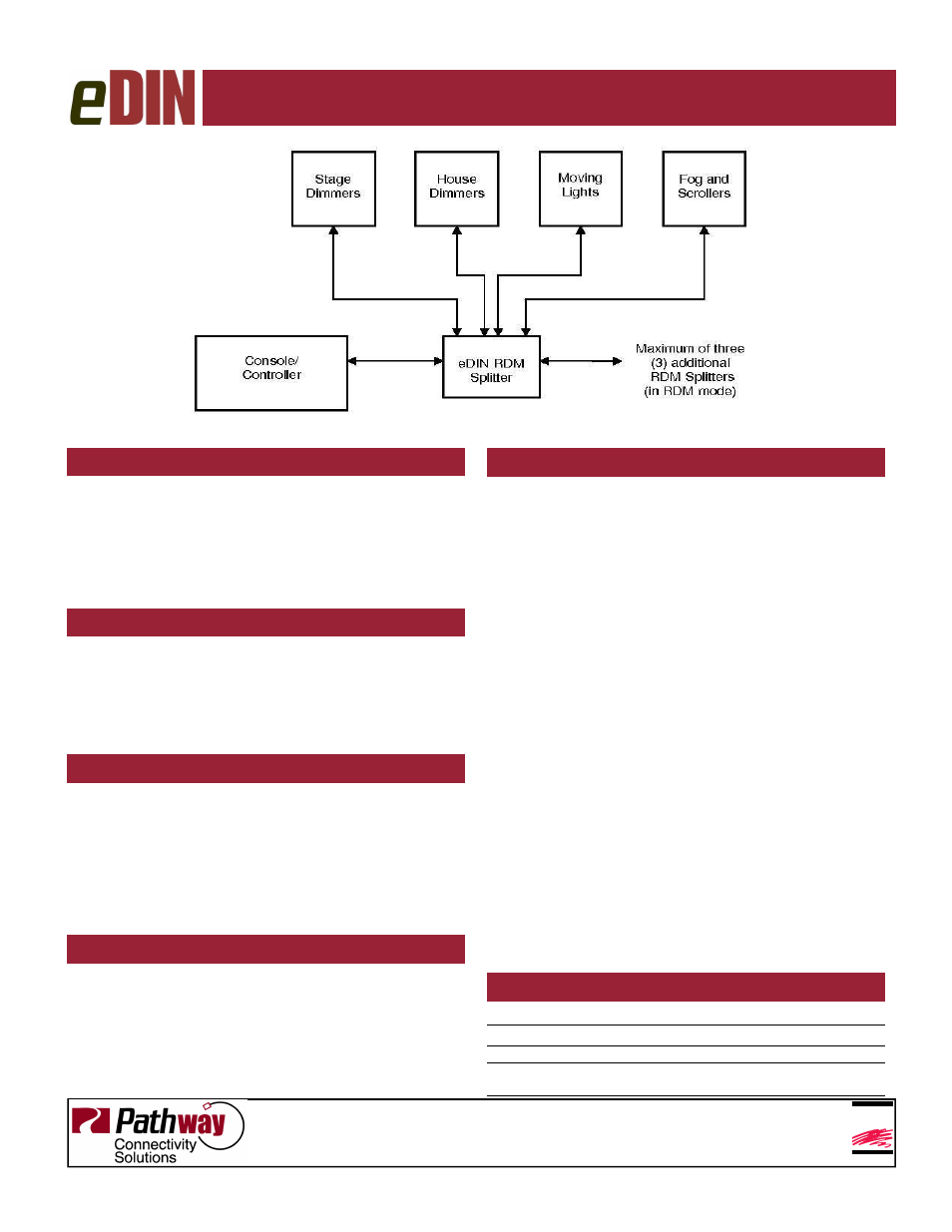
Typical System Layout
RDM ENABLE/DISABLE
RDM RESPONDER FEATURES
The eDIN DMX/RDM Splitter is fully compliant with
ANSI E1.20 as a responder device. An RDM controller,
such as the Pathway DMX Repeater Pro will discover
and retrieve the module’s unique identifier (UID) and its
firmware version. The module is fully discoverable and
configurable even with the RDM switch in the ‘disable’
position.
DMX THRU CONNECTOR
The DMX Thru connector is an active pass through and
fully supports RDM. Due to timing restrictions in the
RDM standard, no more than four (4) eDIN DMX/RDM
Splitters may be daisy-chained together in one run. If
RDM is disabled on all cards, up to eight (8) modules
may be daisy-chained
Some legacy DMX equipment does not check the start
code of data packets on the network and may treat
RDM data as if it were DMX levels. When the RDM
switch is in the ‘disable’ position, the eDIN DMX/RDM
Splitter will filter out all RDM packets, preventing down-
stream legacy equipment from acting unpredictably.
The module should have the power cycled whenever
the RDM switch is returned to the ‘enable’ position.