頁面 5, 8v dc bias, Out in (12~15v) – MIPRO ACT-818 Wideband Single-Channel Digital Receiver User Manual
Page 5: Out in made in taiwan (12~15v) lift, Gnd mic line, Receiver installation
4
5
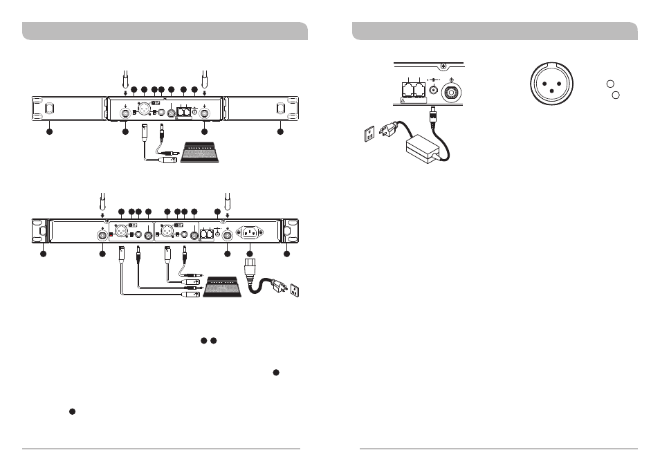
Antenna Installation:
!
Install 2 separate antennas on the antenna sockets on the rear panel.
illustrated in (Figure 1/Figure 2).
Connecting the power supply:
!
AC Power Operation: Connect the AC power cable to the AC Input Jack , then
plug the other end into an AC outlet having the correct voltage and rating, (See
Figure 2)(ACT-828)
!
DC Power Operation: Connect the output end of AC/DC power supply to DC 12V
Input Jack , then plug the power supply unit into an appropriate AC outlet as
shown in (Figure 3). (Caution: Be sure the power supply is connected to an AC
outlet with the correct voltage and rating.)
19
17
10 18
Receiver Installation
(Figure 2)
(Figure 1)
Wideband Digital Receivers
Wideband Digital Receivers
+8V DC BIAS
ANTENNA B
BALANCED OUT CH2
BALANCED OUT CH1
LIFT
LIFT
OUTPUT CH2
OUTPUT CH1
SPDIF OUT CH2
SPDIF OUT CH1
GND
GND
MIC
MIC
LINE
LINE
This connector can not be connected
to telecommunication networks.
REMOTE
OUT
IN
(12~15V)
DC INPUT
+8V DC BIAS
ANTENNA A
AC INPUT: 100~240V
MADE IN TAIWAN
+8V DC BIAS
+8V DC BIAS
ANTENNA A
ANTENNA B
This connector can not be connected
to telecommunication networks.
REMOTE
OUT
IN
MADE IN TAIWAN
(12~15V)
LIFT
OUTPUT
SPDIF OUT
GND
MIC
LINE
BALANCED OUT
DC INPUT
9
9
10
10
11
14
14
14
18
19
9
9
13
13
13
15
15
15
16
17
17
12
12
12
18
ACT-818
ACT-828
Audio Output Connection:
Level Switch Setting Position for Unbalanced Output:
!
When connecting from receiver's unbalanced output to the “LINE-IN” jack of a mixer
or amplifier or “Electric Guitar”, switch the Level Switch to “LINE” position. Low
sensitivity may occur if switch to the wrong level position. When connecting from
receiver's unbalanced output to the “MIC IN” jack of a mixer or amplifier; switch the
Level Switch to “MIC” position. Louder or quieter volume of microphone may occur
if switch to the wrong level position. When using electric guitar, don't use “MIC”
position as it may have generated insufficient level.
Connection Method of Unbalanced Output:
!
When receiver and mixer/amplifier is under short distance. Or the connectors of
receiver/mixer/amplifier are "PHONE” types. Using audio output cable attached with
“PHONE PLUG” type, connect one end from the unbalanced output jack, of the
receiver, and the other end to the “LINE-IN” input jack of the mixer/amplifier, as
shown in (Figure 1/Figure 2).
!
Balanced Output Switch: 2 levels of output gain are available: LINE or MIC
Select the most appropriate output level to interface with your mixer or amplifier. If
distortion is experienced, adjust the level control to a lower setting until the desired
output is attained.
!
Balanced Output: Using audio output cables with 3 pin "XLR" type connectors,
connect one end to the balanced output socket of the receiver, and the other end to
the "MIC IN" input of the mixer or amplifier, as shown in (Figure 1/Figure 2). (The
configuration of the 3-pin connector is as shown in (Figure 4))
!
Electric Guitar Output: Using an XLR to 1/4” Jack type connector cable (use Pins 1
and 2 only) connect to guitar input socket on amplifier. Make sure that the gain
level is set at 0dB on both receiver and transmitter.
This connector can not be connected
to telecommunication networks.
REMOTE
OUT
IN
(12~15V)
DC INPUT
+8V DC BIAS
ANTENNA A
(Figure 3)
-
1: GND
2: HOT
3: COLD
+
3
2
1
(Figure 4)