頁面 4, 8v dc bias, Out in (12~15v) – MIPRO ACT-818 Wideband Single-Channel Digital Receiver User Manual
Page 4: Out in, 12~15v) lift, Gnd mic line, Receiver controls and indicators, Front panel, Rear panel, Wideband digital receivers
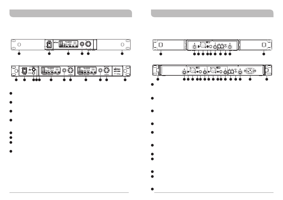
Rack-Mount Brackets: Fits into a standard 19-inch rack case.
Optional MIPRO FBC-71 rear-to-front cables can be installed for front antenna
placement to improve reception quality.
Rear Antenna B Input Connector: The B antenna installs directly to this
connector and also provides power to an optional antenna booster (AT-70B) or
active antenna (AT-90W/AT-70W).
Lift/GND switch (CH2/CH1).
GND: Pin 1 of XLR connector is grounded;
LIFT: Pin 1 of XLR connector is not grounded. (GND = default value).
Balanced Audio Output Socket (CH2/CH1): 3 pin XLR type connector provides
balanced audio output signal same as microphone sensitivity level.
Mic/Line Switch (CH2/CH1): Controls analog balanced output & unbalanced
output level.
MIC level is microphone output level (0dB); LINE level is auxiliary output.
Unbalanced Audio Output Jack (CH2/CH1): 6.3mm (1/4”) phone-jack type
connector provides unbalanced audio output signal.
Digital Output (CH2/CH1): SPDIF Digital Output.
Network Interface Connector: Mipro proprietary comms bus to link receiver(s) to
the optional computer system-monitoring program. (Requires MIPRO Serial or USB
adapter included with software package)
DC Input Jack: Accepts +12V DC (center pin is positive and sleeve is ground).
Rear Antenna A Input Connector: The A antenna installs directly to this
connector and also provides power to an optional antenna booster (AT-70B) or
active antenna (AT-90W/AT-70W).
AC Mains Power Socket: 100 ~ 240V AC.
2
3
Front Antenna A/B Input Connector Access: Allows fitting of an optional FBC-71
rear-to-front antenna kit to enable front antenna placement.
Power Switch and Indicator: Powers the receiver on or off. When switch is turned
on, the red indicator illuminates and VFD panel will light up.
Headphone Jack: 1/4” stereo headphone jack to monitor the receiver output
signal.
Headphone Volume Control and Channel Selector: Push the knob to select the
channel you would like to monitor; turn the knob to adjust the volume of the stereo
headphone.
Channel Indicator: Indicates the specific channel being monitored.
Receiver Display Screen: Color VFD (Vacuum Fluorescent Display).
ACT Button & IR Port: Press and release ACT button syncs the transmitter and
receiver frequency automatically.
Rotary Knob: Selects and sets the parameters.
1
2
3
4
6
5
7
8
Receiver Controls and Indicators
Front Panel
Receiver Controls and Indicators
Rear Panel
9
10
11
12
13
14
15
16
17
18
19
Wideband Digital Receivers
Wideband Digital Receivers
1
1
2
6
2
3
5
6
6
7
7
7
8
8
8
1
1
ACT-818
ACT-828
PUSH FOR MODE
ACT
DIGITAL WIRELESS RECEIVER
PARAMETER
ACT-818
MHz
L
ACT
RF
AF
SQ
ANT
ADD
EQ
CH
GRP
BA
BA
MHz
L
ACT
RF
AF
SQ
ANT
ADD
EQ
CH
GRP
BA
BA
MHz
L
ACT
RF
AF
SQ
ANT
ADD
EQ
CH
GRP
BA
BA
4
+8V DC BIAS
ANTENNA B
BALANCED OUT CH2
BALANCED OUT CH1
LIFT
LIFT
OUTPUT CH2
OUTPUT CH1
SPDIF OUT CH2
SPDIF OUT CH1
GND
GND
MIC
MIC
LINE
LINE
This connector can not be connected
to telecommunication networks.
REMOTE
OUT
IN
(12~15V)
DC INPUT
+8V DC BIAS
ANTENNA A
AC INPUT: 100~240V
MADE IN TAIWAN
+8V DC BIAS
+8V DC BIAS
ANTENNA A
ANTENNA B
This connector can not be connected
to telecommunication networks.
REMOTE
OUT
IN
MADE IN TAIWAN
(12~15V)
LIFT
OUTPUT
SPDIF OUT
GND
MIC
LINE
BALANCED OUT
DC INPUT
ACT-818
ACT-828
9
10 11
14
18
9
13
15
16
17
12
9
10 11
11
14
14
19
9
13
13
15
15
16
17
12
12
18