頁面 10, Eq: capsule equaliser setting, Wideband digital receivers – MIPRO ACT-818 Wideband Single-Channel Digital Receiver User Manual
Page 10
14
15
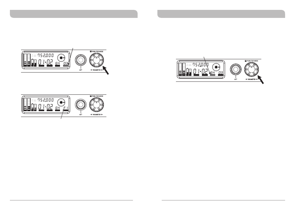
EQ: Capsule Equaliser Setting
Operating Procedure:
1. Press the rotary controller to activate and move the cursor to the EQ parameter.
When the EQ cursor starts to flash, the Equalizer is ready to be set.
2. Rotate the rotary controller clockwise to increase the Equalizer number;
counterclockwise to decrease the Equalizer number.
3. The first digit in EQ parameter will be either F or 0. F denotes anti-feedback is
activated and 0 denotes anti-feedback is not activated.
4. The second digit in EQ parameter denotes the selected Equalizer number. A total of
10 EQ numbers are available starting with 0 and ends with 9. Numbers 0 ~ 8 are
preset EQs and number 9 is user-defined. 0 is the default EQ number.
NOTE: There are 9 preset and 1 user-defined built-in equalisers (00-09). EQ “00” is
the default EQ for the factory fitted MIPRO handheld microphone capsule.
EQ's “01-08” are eight other simulated microphone capsule presets. EQ “09”
is user-defined and can be programmed by the user. However, the receiver
needs to be set up and interfaced with a PC and MIPRO software before this
can be achieved.
The EQ parameter is used to select from a range of simulated microphone capsule EQ's.
The default setting for the factory fitted MIPRO capsule is “00”
EQ cursor starts flashing
Turn clockwise to increase by one number
Turn counterclockwise to decrease by one number
“F” denotes anti-feedback feature is activated
“0” denotes anti-feedback feature is not activated
Wideband Digital Receivers
Wideband Digital Receivers
ADD: Address Setting for PC Remote Control
ADD cursor starts flashing
Rotate clockwise to increase by one number (01-64)
Rotate counterclockwise to decrease by one number (64-01)
Operating Procedure:
1. Press the rotary controller to activate and move the cursor to the ADD parameter.
When the ADD cursor starts to flash, the Address is ready to be set.
2. Rotate the rotary controller clockwise to increase the Address number;
counterclockwise to decrease the Address number.
3. Press the rotary controller once to confirm and save the selected Address number.
NOTE: This receiver is equipped with an ACT-BUS interface. It allows users to use
the MIPRO-DV (interface converter) and software (sold separately with
MIPRO-DV) for remote PC monitoring. It can monitor up to a maximum of
64 channels at the same time. The receiver module address can be set from
1 to 64. In order to monitor the system remotely, each channel must have
its own address for individual identification. If two or more channels have
been assigned the same address, it will cause confusion in the monitoring
system. If the system is not under PC monitoring/control, identical addresses
will not affect the receivers' operation.
For normal “stand-alone” use, this parameter does not need to be set. However when
multiple receivers are to be used and controlled remotely using the MIPRO optional
control software each receiver must be given a unique address. Always ensure that you
set this address before adding the receiver to the remote control network.
ACT
ANT
EQ
MHz
L
RF
AF
SQ
ADD
CH
GRP
BA
BA
ACT
ANT
EQ
MHz
L
RF
AF
SQ
ADD
CH
GRP
BA
BA
MHz
L
ACT
RF
AF
SQ
ANT
ADD
EQ
CH
GRP
BA
BA