Group 7 : motor control parameter set (level 3) – Beijer Electronics AN-BEI-H2-038 User Manual
Page 10
APPLICATION NOTE AN‐BEI‐H2‐038
Date: 15/02/12
AN‐BEI‐H2‐038 Modbus RTU Control and Register Mapping
10
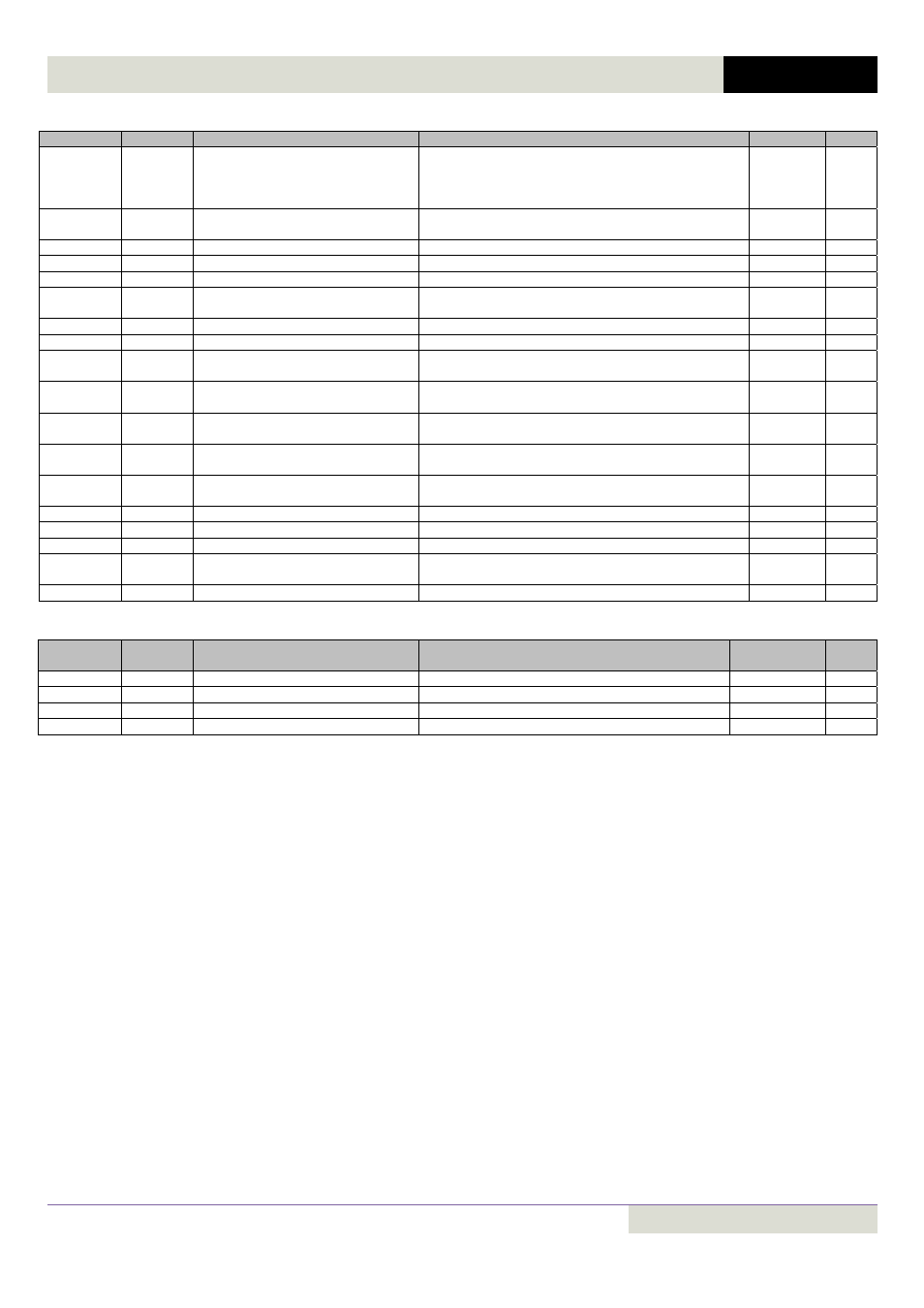
Group 6 : Advanced Parameter set (Level 3)
Par
Register
Description
Range
Scaling
Type
P6‐01
601
Firmware Upgrade enable
0: Disabled
1: Enable (IO and DSP)
2: Enable (IO only)
3: Enable (DSP only)
U16
P6‐02
602
Auto thermal management
0: Disable
1: Enable
U16
P6‐03
603
Auto‐reset delay time
1 to 60
U16
P6‐04
604
User relay hysteresis band
0 ‐ 250
1 = 0.1%
U16
P6‐08
608
Max speed ref frequency
0, 5 to 20
U16
P6‐10
610
Enable PLC operation
0: Disable
1: Enable
U16
P6‐11
611
Speed hold time on enable
0 to 2500
1 = 0.1s
U16
P6‐12
612
Speed hold time on disable
0 to 2500
1 = 0.1s
U16
P6‐18
618
DC injection braking voltage
0 : Auto
0 to 250
0 = Auto
1= 0.1%
U16
P6‐22
622
Reset cooling fan run‐time
0: Disable
1: Enable
U16
P6‐23
623
Reset kWh meter
0: Disable
1: Enable
U16
P6‐24
624
Service time interval
0 … 60 000 h
(0 = disabled)
1=1
U16
P6‐25
625
Reset service indicator
0: Disable
1: Reset
1=1
U16
P6‐26
626
Analog output 1 scaling
0 to 5000
1 = 0.1
U16
P6‐27
627
Analog output 1 offset
‐5000 to 5000
1 = 0.1%
S16
P6‐28
628
P0‐80 display value index
0 to 127
U16
P6‐29
629
Save User Parameters as default
0: Disable
1: Enable
U16
P6‐30
630
Level 3 access code
0 to 9999
U16
Group 7 : Motor Control Parameter set (Level 3)
Parameter
Register
Number
Description
Range
Scaling
Type
P7‐01
701
Motor Stator resistance
Drive dependent
1 = 0.001ohm
U16
P7‐04
704
Motor Magnetising Current
Drive dependent
1 = 0.1A
U16
P7‐11
711
Pulse width minimum limit
0 to 500 (Time = value *16.67ns)
1 =1
U16
P7‐12
712
V/F mode magnetising period
0 to 2000
U16