Prepare for post sleeves, Measure, mark & drill for brackets, Install brackets – AZEK Straight Rail User Manual
Page 2: Hardware, Parts tools required, Straight rail installation guidelines for, Important, Page 2, Top retainer, Bottom rail
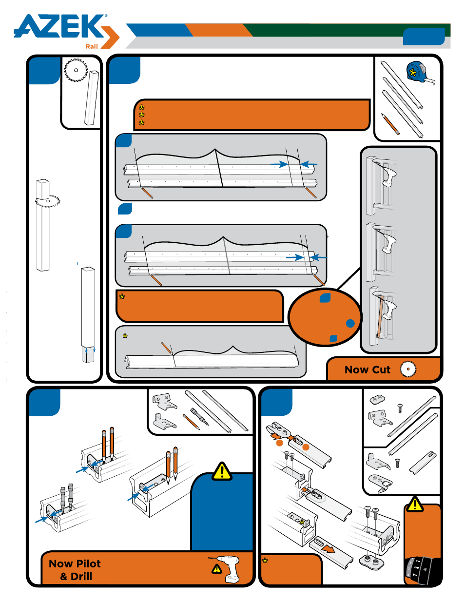
(1) Handrail
Hardware
1
Parts
Tools Required
Pencil
Measuring
Tape
Drill
Recommended:
Impact Driver
Mitre Saw
fitted with a
high tooth
count finish
carpentry blade
1/8”
Drill
Bit
5/16”
Drill
Bit
(2) Top Rail
Straight Bracket
(2) Threaded
Plates
(2) Spring Clip Threaded
Plate Retainer
(2) Bottom Bracket
Base
(2) Bottom Bracket
Flange + Set Screw
.
(5) 1” #8 Wood
Screws
(8) 5/8” #10 Machine
Screws
(1) Spring Clip
Installation Tool
Trademark Profiles Shown
Throughout Instructions
Balusters
(13) 6’ Kit or (18) 8’ Kit
US:
(1) 4 3/8”
Center Support
Canada:
(1) 2 3/8”
Center Support
Premier
Top Rail
Reserve
Top Rail
(1) Top Retainer
(1) Bottom Rail
Premier
Bottom
Rail
Reserve
Bottom
Rail
(1) 3/16” Allen Key
(1) T-25 Bit
(2) Baluster Swing
Brackets
(1) Center Support
Bracket
Baluster Screws
(28) 6’ Kit
(38) 8’ Kit
(8) 2 1/2” #10 Wood
Screws
Prepare for
Post Sleeves
3/16”
Drill
Bit
• The 4 x 4 should be completely “boxed in” around all 4 corners of the
firmest attachment.
• Make sure posts are level and plumb.
• If post is twisted or oversized, trim as necessary so post sleeve slides
easily over post. (Do not force sleeve over post)
• Post sleeves may also be used over wood posts installed with Surface
Mount Bracket or over Tallboy Surface Mount Bracket.
• Post sleeves should not be notched for installation.
• If installing using a Surface Mount Bracket or Tallboy Surface Mount
Bracket, please refer to those specific installation instructions.
• IMPORTANT: Must check with local building code for proper installation
of wood post and decking attachment.
WARNING: Post sleeves are not designed to be used in
structural applications. Therefore, they should not be used
where they may be subject to weight bearing applications
such as supports for a roof of a porch or deck.
IMPORTANT
Make sure that the
DRIVE TOOL/DRILL
is configured or set
to use the SCREW
setting when driving
and/or tightening all
FASTENERS.
STRAIGHT RAIL INSTALLATION GUIDELINES for
AZEK Premier
AZEK Trademark
AZEK Reserve
Page 2
© 2013 AZEK Building Products. All rights reserved
Top Retainer
1
16
1
16
Hand Rail can be cut from either end
2
3
Remove install-
ation tool before
fully tightening
bracket screws
5
Top Retainer
Bottom Rail
When
drilling holes
for brackets,
do not drill
through top
surface of
bottom rail.
Measure, Mark
& Drill for
Brackets
Mark Bracket
1/16” from end
of Retainer
Pilot with 1/8” Drill Bit
Drill with 5/16“ Drill Bit
Mark Bracket
1/8” from end
of Bottom Rail
Consideration:
For Aluminum Top Retainer
use automatic center punch.
Cut Post
Sleeves
Measure & Mark Top Retainer, Bottom
Rail, & Handrail Ensuring Proper Hole
Spacing .... And Cut
Cut
Post Sleeve
minimum 2”
longer than
desired railing
height
Do not
force the
Post Sleeve
over the 4 x 4
as it may
eventually lead
to a crack or
split
X is
greater
than 3 1/8”,
NO
Swing
Bracket
Required
X is
less than
3 1/8”,
Swing
Bracket
IS
Required
Swing
Bracket
In Use
b
Rail Center Between Holes
X
a
Rail Center On Hole
If X is greater than 4 3/8”, Composite Baluster spacing will not meet Code.
If X is greater than 4 1/8”, Metal Baluster spacing will not meet Code.
Shift Rail Center from (a) Center on Hole to (b) Center Between Holes.
a
X
b
If X is less than 3 1/8”,
use Baluster Swing
Brackets in Step
to allow access in
Step
6a
13
Ensure Posts are square and plumb
Take measurements between bottom of posts for more accurate rail length
Leave Handrail 1/16” longer than Top Retainer for a tight fit
4
X 2
X 2
Install
Brackets
Bottom Rail
Bottom
Rail
X 4
X 4
X 2
X 2
X 2
Spring Clip
Installation Tool
Top
Retainer
1
2
Close Spring
Clip and
insert into
Installation
Tool
X 2
Most building codes require that a 4” sphere shall
not pass through the rail at any point.
To comply with 4” sphere rule, a 6 ft. section must
be cut a minimum of 7/8”.
IMPORTANT
Make sure that
the DRIVE
TOOL/DRILL is
configured or set
to use the
SCREW setting
when driving
and/or tightening
all FASTENERS.