Vaddio WallVIEW HD-20 User Manual
Page 7
WallVIEW HD-20
WallVIEW HD-20 Manual 342-0179 Rev. C
Page 7 of 16
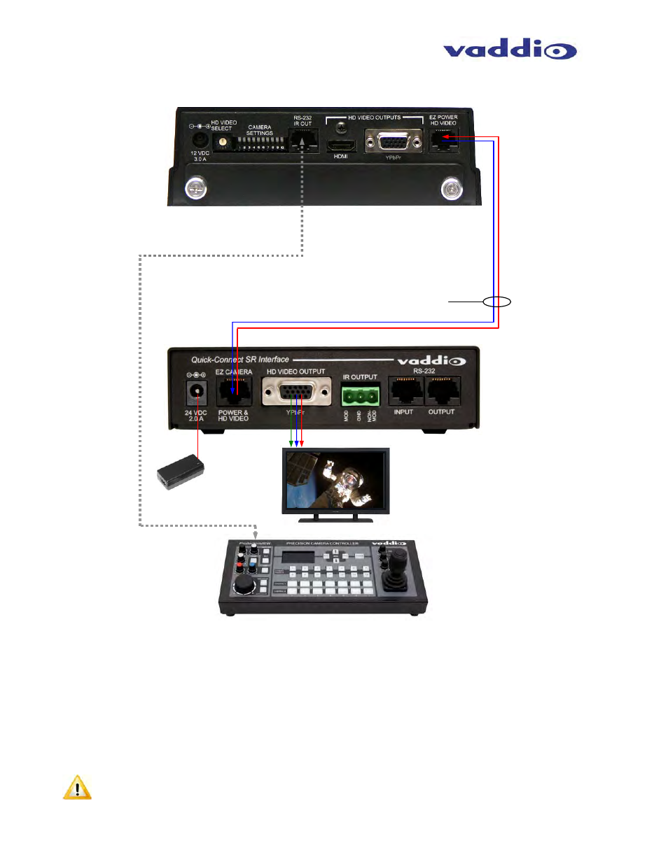
Basic Wiring Configuration of the WallVIEW HD-20 to a Vaddio Joystick Controller
Mounting and Installation Instructions for the CONCEAL Wall Mounting System:
Step 1: Determine Camera Mount Location
When locating the camera, consider viewing angles, lighting conditions, possible line of site obstructions and
check for in-wall obstructions where the camera is to be mounted. Pick a mounting location to optimize the
performance of the camera. After determining the optimum location of the camera system, route the required two
(2) Cat-5e cables from the camera to the head-end.
The two (2) Cat-5e cables should feed-through a 1” (25.4mm) opening (circular or square shape) centered in the
rectangular slot located on the rear flange of the CONCEAL Wall Mount Bracket (see Fig. 1).
Note: Do not cut out the entire rectangular slot opening in the wall! This will not allow the two-lower wall
anchors to correctly fasten the Conceal Wall Mount to the wall (see Fig. 1).
RS-232
Cat-5e
Rear Panel
Quick-Connect SR Interface
(Equipment Head-end)
YPbPr & Power on one (1) Cat-5e up to 100’ (30.5m)
YPbPr
24VDC, 2.0 A
PowerRite Power
Supply
HD Monitor
(Really Simulated Feed)
ProductionVIEW Precision Camera Controller
←
YPbPr (HSDS differential)
Power
→
Rear
Panel
HD-20