Vaddio EZIM CCU Slot Card User Manual
Page 8
WallVIEW CCU HD-18
WallVIEW CCU HD-18 Manual 341-889 Rev. C
Page 8 of 18
INSTALLATION
The WallVIEW CCU HD-18 product was specifically designed for installation on a vertical wall surface
with CAT-5 cable connectivity for Power, Video and Control signaling (three cables are required).
Installation is simplified in that no custom 8-Pin mini-din cables or expensive S-Video plenum cables are
needed and no power outlets are required near the camera bracket. All cabling is routed to the head-end
using CAT-5 cables. The use of “pass-thru” RJ-45 connectors should not be used (see notice on page 2).
Before Installing
• Locate the camera mounting location paying close attention to camera viewing angles, lighting
conditions, possible line of site obstructions, and checking for in-wall obstructions where the camera
is to be mounted. Pick a mounting location to optimize the performance of the camera.
• Pre-wire all cabling as required (see the wiring diagram example below).
• The Thin Profile Wall Mount for the WallVIEW CCU HD-18 can be mounted directly to a 2-gang wall
box or can be mounted to the drywall using four dry wall anchors.
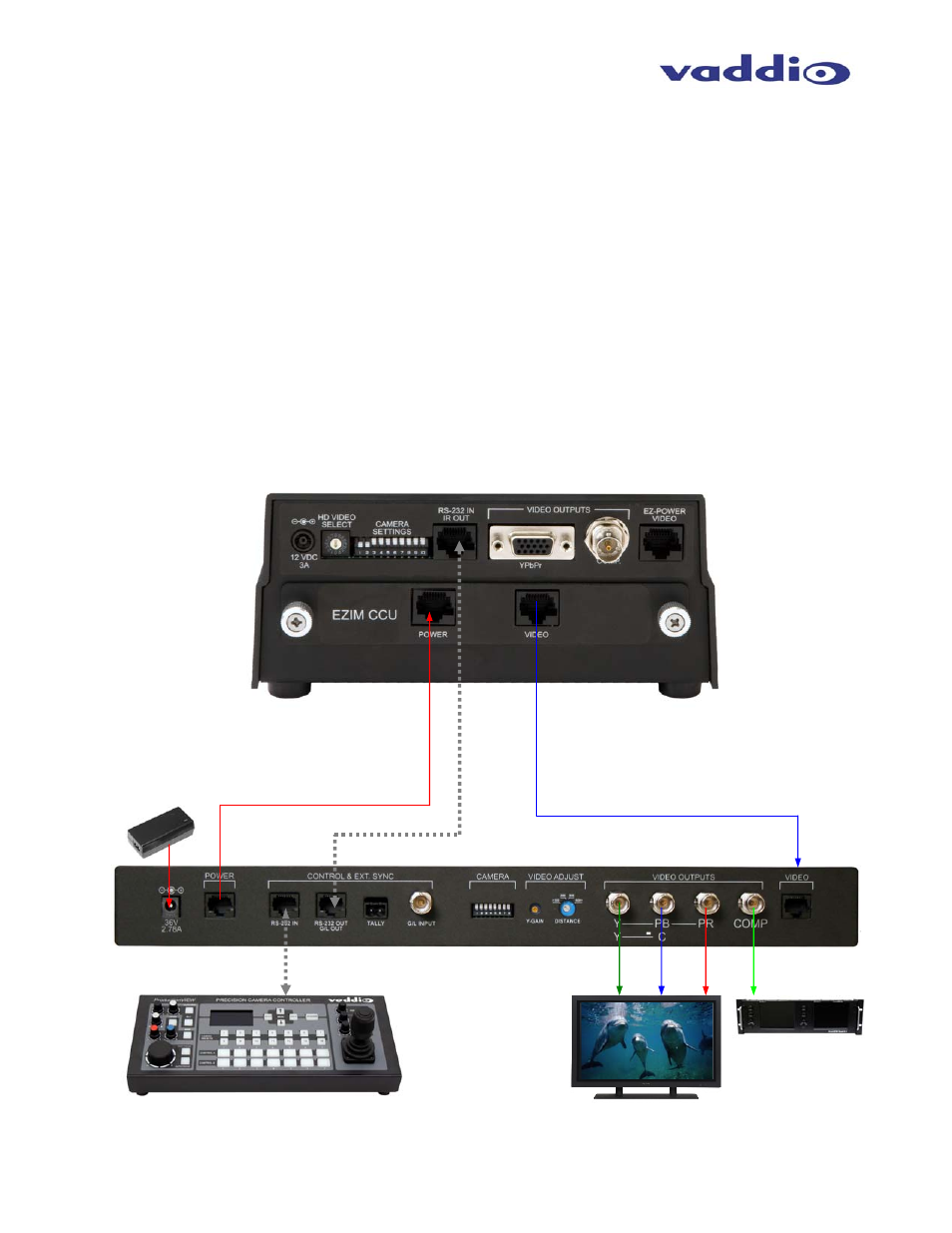
Connecting the EZIM CCU to the EZIM CCU Slot Card in the HD-18 Camera
Vaddio Precision Camera Controller
RS-232
RS-232
YPbPr and CVBS (4pr.)
Power (4pr.)
PS - 36VDC
Rear Panel
HD-18 with
EZIM CCU
Slot Card
YPbPr
CVBS
HD Monitor
(Simulated Feed)
SD Monitor