Installation – Pitco Frialator 35 Series User Manual
Page 8
INSTALLATION
L20-290 Rev 3, (5/12)
5
Lighting Instructions (continued)
d.
If the pilot goes out, wait 5 minutes and repeat step C. If after three tries
the pilot will not remain lit, refer to the operator troubleshooting section of
this manual.
e.
Once a pilot flame has been established, turn the gas valve knob
counterclockwise to the ON position.
f.
Set the thermostat control knob to the desired temperature setting.
The main burners will ignite and be controlled by the thermostat.
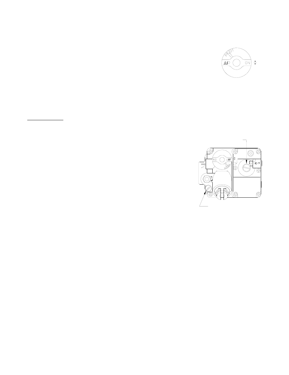
Pilot Flame Adjustment
For manual pilots, refer to the following instructions. Perform this procedure once the pilot is lit.
NOTE: This procedure requires a DC millivolt meter set to a scale of 0-1000 mV.
Using test leads with sharp probes will help in taking the required readings.
a.
Locate the thermopile wires coming from the thermostat/limit
box going to the gas valve. The wire size decreases near the
gas valve connections.
b.
Using the positive (+) test probe, connect the probe to the high
limit wire terminal. On UFM systems, pierce the high limit wire
insulation, with the tip of the test lead probe, at the gas valve
safety magnet connection.
c.
Connect the negative (-) test probe to the pilot tubing.
d.
Remove the cap screw located below the pilot tubing on the
gas valve. The pilot flame adjustment screw is recessed
behind this. Turning the pilot flame adjustment screw clockwise
lowers the pilot flame and millivolt output. Turning the pilot flame
adjustment screw counter- clockwise increases the pilot flame size
and millivolt output.
e.
While monitoring the DC millivolt meter, rotate the pilot flame adjustment screw in the
direction necessary to achieve a reading of 25 ± 5 mV.
Note: Allow 3 to 5 minutes between flame adjustments to allow the reading to stabilize.
f.
Replace the cap screw.
Main Burner System Adjustment
For the main burners to operate the gas supply valve must be open and the thermostat must be turned
on. For models with electric controls, the main power switch must be on. The main burners receive gas
from the main gas supply through the thermostatically controlled valve. When the thermostat is turned up
the gas control valve opens.
The main burner pressure must be adjusted to deliver optimum flame. Refer to the following procedure to
adjust the main burners.
REGULATOR ADJUSTOR
(UNDER CAP SCREW)
PILOT ADJUSTOR
(UNDER CAP SCREW)