Installation – Pitco Frialator 35 Series User Manual
Page 5
INSTALLATION
2
L20-290 Rev 3, (5/12))
Heat Deflector Installation
If the appliance requires a heat deflector, you will find a removable label at the rear top edge of the unit. This
label has instructions for positioning and installation of the heat deflector. Refer to the label and the instructions
below to install the deflector.
a.
Remove the two self-drilling screws from the top, back area of the appliance.
b.
Position the heat deflector so that the angled portion of the deflector is facing toward the front of
appliance. Secure the heat deflector to the back of the unit using the two previously removed
fasteners
.
c.
When properly installed the angled section of the heat deflector will extend over the flue
opening to redirect the heat. It SHOULD NOT cover the flue opening. Never allow anything to
block the flue opening; this will cause the appliance to over heat and inhibit proper combustion,
which could produce dangerous gases
INSTALLATION
If you have completed the above steps that are applicable to the appliance you purchased, the appliance is now
ready to be installed. Although it may be possible for you to install and set up your new appliance, it is
STRONGLY recommended that you have this done by qualified professionals. A qualified professional will
ensure that the installation is safe and meets local building and fire codes.
WARNING
DO NOT obstruct the flow of combustion, ventilation or air openings around the appliance.
Adequate clearance around the appliance is necessary for servicing and proper burner
operation. Ensure that you meet the minimum clearance requirements specified in this
manual.
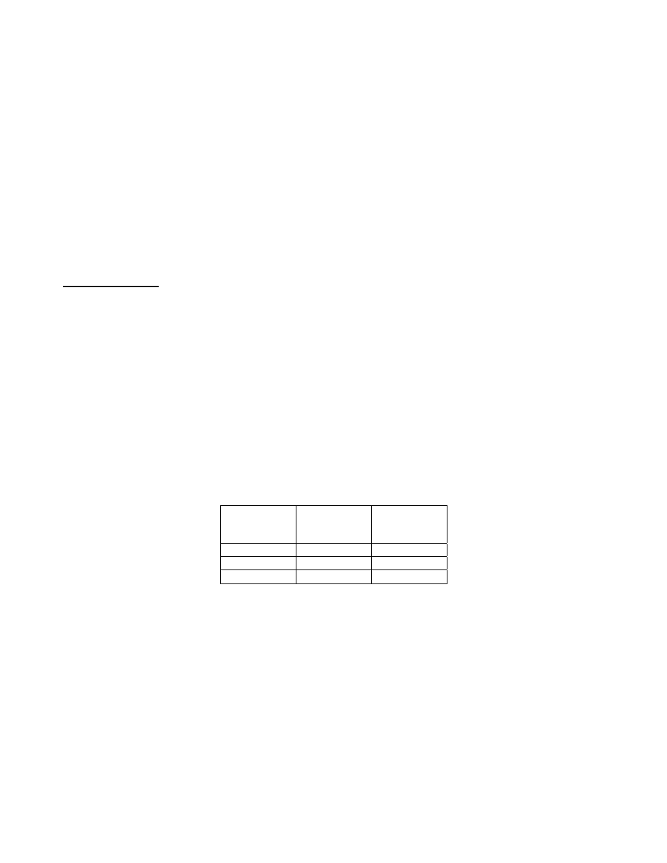
Installation Clearances
The clearances shown below are for combustible and non-combustible installations and will allow for safe and
proper
operation of your appliance.
Combustible
Construction
Non-
Combustible
Construction
Back
6 in. (15 cm)
0
Sides
6 in. (15 cm)
0
Floor
4 ¾ (11.5 c,)
4 ¾ (11.5 cm)
In addition to the above clearances there must also be at least 28 inches (71 cm) of aisle space in front of the
appliance.
Gas Connection
Your appliance will give you peak performance when the gas supply line is of sufficient size to provide the
correct gas flow. The gas line must be installed to meet the in accordance with AS/NZS 5601 or local codes, as
applicable. Gas line sizing requirements can be determined by a qualified installation professional, your local
gas company or by the Technical Regulator. The gas line needs to be large enough to supply the necessary
amount of fuel to all appliances without losing pressure to any appliance. A properly sized and installed gas line
will deliver a minimum supply pressure of 7.0 ± 2.0 inches w.c. (1.75 ± 0.5 kPa) for natural gas and 12.0 ± 2.0
inches (3.0 ± 0.5 kPa) for propane to all appliances connected to the supply line, operating simultaneously at full
demand. Each appliance is equipped to operate on one certain fuel type. The type of fuel with which the
appliance is intended to operate is stamped on the data plate, which is attached to the inside of the door.