Ariens 921006 - ST1130DLE User Manual
Page 32
GB - 32
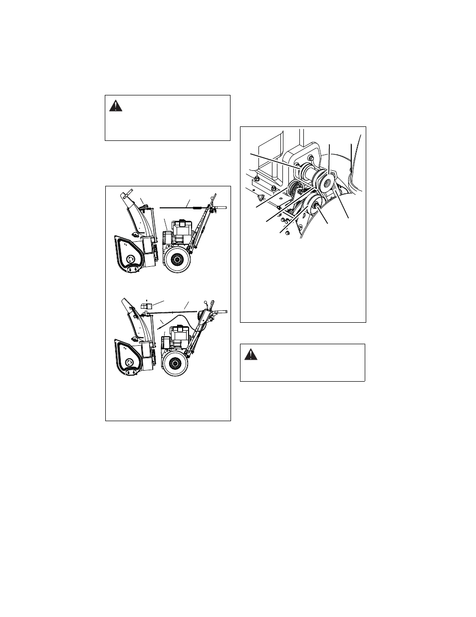
8. Remove hex bolts securing housing to
frame (two on each side). Tip housing
and frame apart on pivot pin (Figure 43).
9. Remove attachment drive belts from
attachment pulley (hold brake away from
belt).
Install new attachment drive belts:
1. Place new attachment belts onto
attachment pulley.
NOTE: Holding down the attachment clutch
lever will make it easier to reconnect the
housing and frame.
2. Tip housing and frame back together
and secure with hex bolts.
3. Place belts onto engine sheave.
4. Reposition and secure belt finger.
IMPORTANT: With clutch lever engaged, belt
finger on the side opposite the belt idler
should be less than 1/8 in. (3 mm) from belt,
but not touching the belt. Adjust belt finger as
necessary.
5. Check adjustment. See Attachment
Clutch/Brake Adjustment on page 28
6. Reconnect chute crank and secure with
spring clip (921005) or hair pin (921004,
006, 007, 008, 009). Reconnect chute
lock cable and deflector cable (921004,
006, 007, 008, 009).
7. Replace belt cover.
TRACTION DRIVE BELT
REPLACEMENT
NOTE: Replacement will be easier with
housing and frame tipped apart and bottom
cover off.
1. Remove attachment drive belts (see
Attachment Drive Belt Replacement on
page 31).
CAUTION: Always support Sno-
Thro frame and blower housing
when loosening the cap screws
holding them together. Never
loosen cap screws while unit is in
service position.
Figure 43
921005
921004, 006, 007, 008, 009
1. Belt Cover
2. Chute Gear Cover
3. Discharge Chute Rod
4. Chute Lock Cable
1
2
3
4
1
3
2
WARNING: AUGER / IMPELLER
MUST STOP within 5 seconds
when attachment clutch lever is
released or unit damage or serious
injury may result.
Figure 44
OS7198
1. Traction Drive
Belt
2. Engine
Sheave
3. Attachment
Drive Belts
4. Belt Finger
5. Attachment
Belt Idler
6. Attachment
Idler
Adjustment
Nut
7. Traction Belt
Idler
2
1
3
4
5
6
7