Ariens 921006 - ST1130DLE User Manual
Page 31
GB - 31
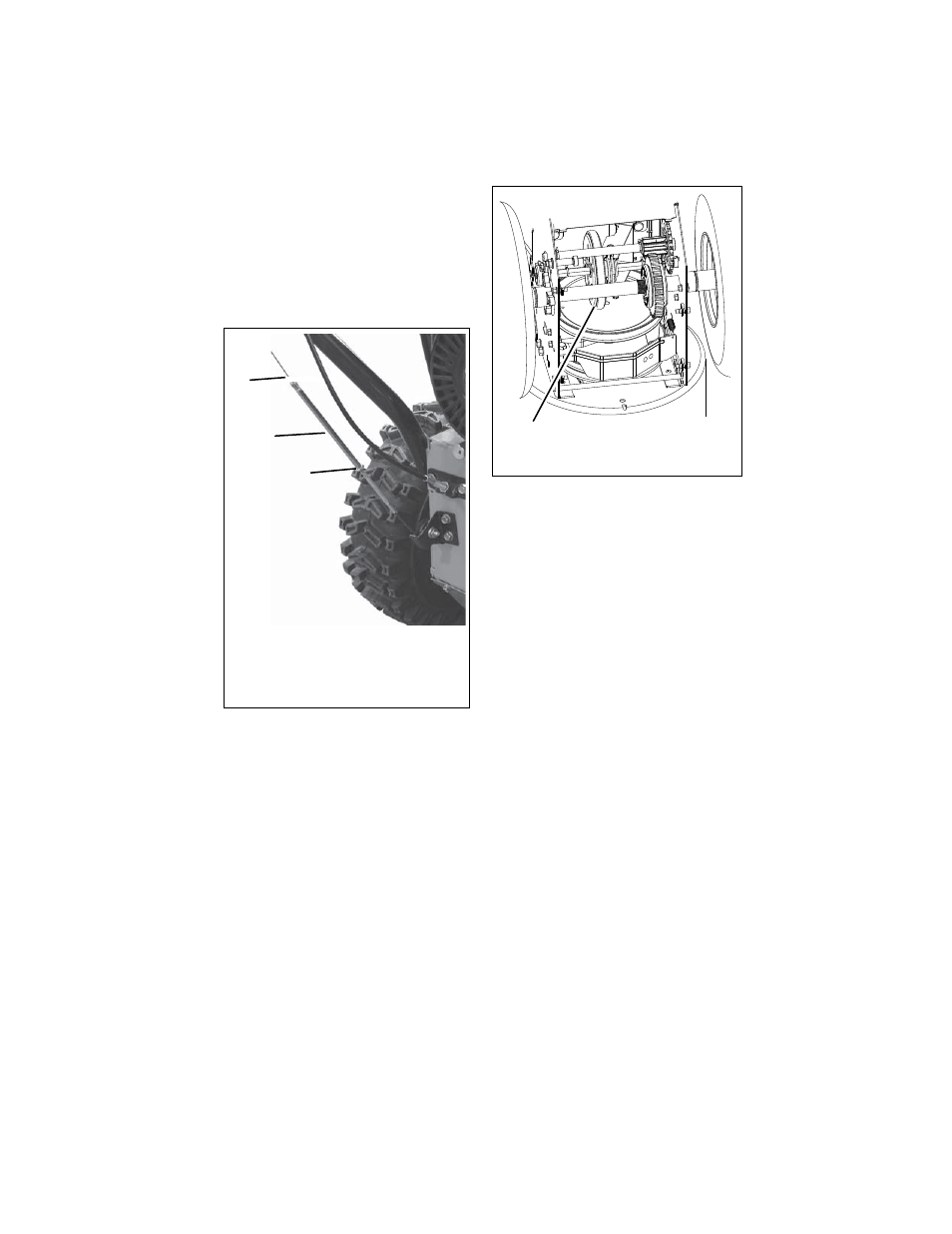
a. With the traction drive clutch
lever disengaged, loosen the jam
nut on the cable adjuster.
b. Turn the adjuster body up the
cable to decrease the distance
between the clutch lever and
handlebar.
c. Turn the adjuster body down the
cable to increase the distance
between the clutch lever and
handlebar.
5. Check the traction clutch lever distance
and repeat adjustment steps if
necessary.
6. Tighten the jam nut on the traction cable
adjustor body.
7. With the clutch disengaged, check that
there is more than 1/32 in. (0.8 mm)
clearance between friction disc and
drive plate assembly (Figure 42).
IMPORTANT: If traction clutch cannot be
adjusted within specified range, see your
Dealer for repairs.
ATTACHMENT DRIVE BELT
REPLACEMENT
Remove old attachment drive belts:
1. Shut off engine, remove key, disconnect
spark plug wire and allow unit to cool
completely.
2. Remove belt cover and chute gear cover
(921004, 006, 007, 008, 009)
(Figure 43).
3. Rotate discharge chute all the way to the
left (as viewed from the operator’s
position).
4. 921004, 006, 007, 008, 009: Remove
hair pin under the control panel
connecting the discharge chute rod to
the chute rotation lever and slide the
discharge chute rod forward.
921005: Remove spring pin from chute
crank and separate.
IMPORTANT: Disconnect chute lock cable
and deflector cable, if equipped (921004,
006, 007, 008, 009).
5. Remove belt finger (Figure 39).
6. Remove attachment drive belt from
engine sheave (it may be necessary to
turn engine sheave using recoil starter
handle).
IMPORTANT: To avoid bending bottom cover
when tipping unit apart, support handlebars
firmly or tip unit up on housing and remove
bottom cover by removing six cap screws
before separating unit.
7. Support Sno-Thro frame and housing.
Figure 41
OS7208
1. Traction Clutch Cable
2. Adjuster Body
3. Jam Nut
2
3
1
Figure 42
OS7144
>1/32 in.
(.8 mm)