American Dryer Corp. AD/ML-310 User Manual
Page 31
113217 - 5
www.amdry.com
31
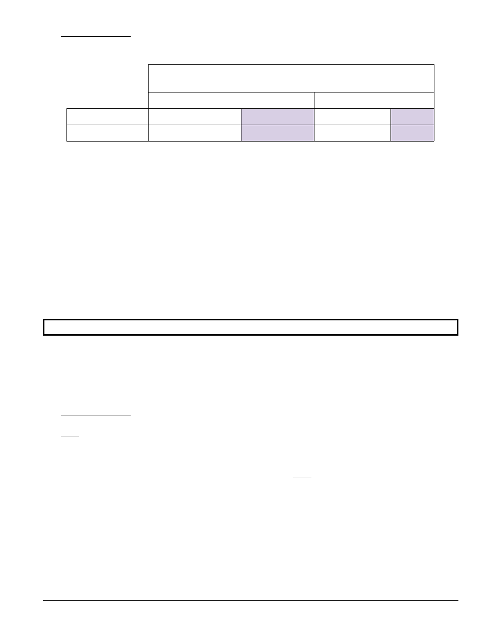
2. Technical Gas Data
a. Gas Specifications
Shaded areas are stated in metric equivalents
* Measured at gas valve pressure taps when the gas valves are on.
b. Gas Connections:
Run a 1-1/2” pipe from the main gas header to the dryer. There is a 1-1/2” gas pipe connection at the bottom
right side of the dryer’s base.
Inlet connection ------------- 1-1/2” N.P.T.
Btu/hr input (per dryer) ---- 1,125,000 Btu/hr (283,500 kcal/hr)
1) Natural Gas
Pressure regulation is controlled by both gas valve’s internal regulators. Incoming supply pressure must
be consistent between a minimum of 6.0 inches (14.92 mb) water column (W.C.) and a maximum of 12.0
inches (29.9 mb) water column.
NOTE: Natural gas model is CSA approved.
2) Liquid propane (L.P.) gas have both of their gas valve’s internal pressure regulators blocked open so that
the gas pressure must be regulated upstream of the dryer. The pressure measured at each gas valve pressure
tap must be a consistent 10.5 inches (26.1 mb) water column. There is no regulator or regulation provided
in an L.P. gas dryer. The water column must be regulated at the source (L.P. tank) or external regulator/
regulation must be added to each dryer.
3. Piping/Connections
ALL components/materials must conform to National Fuel Gas Code Specifications ANSI Z223.1-LATEST
EDITION, or in Canada, CAN/CGA-B149.1-M91 (Natural Gas) or CAN/CGA-B149.2-M91 (Liquid Propane
[L.P.] Gas) or LATEST EDITION (for General Installation and Gas Plumbing), as well as local codes and ordinances
and must be done by a qualified professional. It is important that gas pressure regulators meet applicable pressure
requirements, and that gas meters be rated for the total amount of ALL the appliance Btu being supplied.
The dryer is provided with a 1-1/2” N.P.T. inlet pipe connection located at the right side of the base of the dryer.
For ease of servicing, the gas supply line of each dryer must have its own shutoff valve.
The size of the main gas supply line (header) will vary depending on the distance this line travels from the gas
meter or, in the case of L.P. gas, the supply tank, other gas-operated appliances on the same supply line, etc.
Specific information regarding supply line size should be determined by the gas supplier.
S
A
G
F
O
E
P
Y
T
L
A
R
U
T
A
N
E
N
A
P
O
R
P
D
I
U
Q
I
L
e
r
u
s
s
e
r
P
d
l
o
f
i
n
a
M
*
.
C
.
W
s
e
h
c
n
i
5
.
3
b
m
7
.
8
.
C
.
W
s
e
h
c
n
i
5
.
0
1
b
m
1
.
6
2
e
r
u
s
s
e
r
P
e
n
i
L
-
n
I
.
C
.
W
s
e
h
c
n
i
0
.
2
1
-
0
.
6
b
m
9
.
9
2
-
2
9
.
4
1
.
C
.
W
s
e
h
c
n
i
0
.
1
1
b
m
4
.
7
2