Avaya P332G-ML User Manual
Page 36
Chapter 4
Installation
22
Avaya P332G-ML User’s Guide
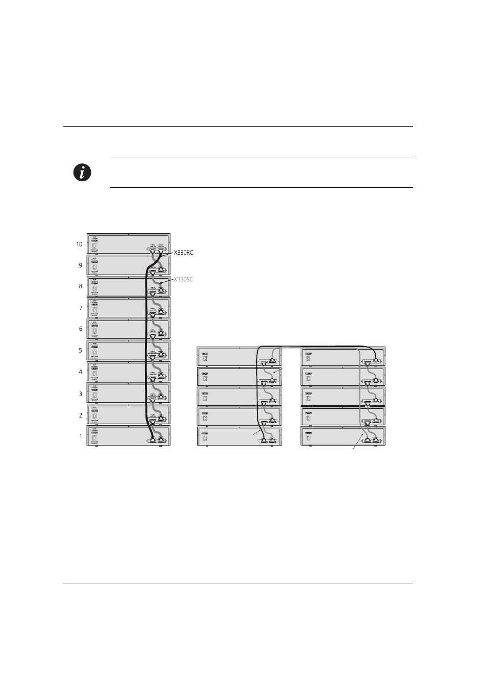
Note:
Figures 4.2 and 4.3 show the back panel of a P330 switch AC version. These
drawings also apply to the P330-ML products.
Figure 4.3
P330 Stack Connections
Cable to
Upper Unit
Cable to
Lower Unit
Cable to
Upper Unit
Cable to
Lower Unit
Cable to
Upper Unit
Cable to
Lower Unit
Cable to
Upper Unit
Cable to
Lower Unit
Cable to
Upper Unit
Cable to
Lower Unit
Power Supply
Connector
BUPS
Connector
Power Supply
Connector
BUPS
Connector
Power Supply
Connector
BUPS
Connector
Power Supply
Connector
BUPS
Connector
Power Supply
Connector
BUPS
Connector
5
4
3
2
1
Cable to
Upper Unit
Cable to
Lower Unit
Cable to
Upper Unit
Cable to
Lower Unit
Cable to
Upper Unit
Cable to
Lower Unit
Cable to
Upper Unit
Cable to
Lower Unit
Cable to
Upper Unit
Cable to
Lower Unit
Power Supply
Connector
BUPS
Connector
Power Supply
Connector
BUPS
Connector
Power Supply
Connector
BUPS
Connector
Power Supply
Connector
BUPS
Connector
Power Supply
Connector
BUPS
Connector
10
9
8
7
6
X330RC
X330SC
X330LC