Specifications, Maintenance, Warranty and customer service – ADTRAN 850 User Manual
Page 3: Figure 3. alternate mounting arrangements, Table 3. specifications, 48 r, 48 v
3
Section 61175043L2-5, Issue 1
61175043L2-5A
There are three installation arrangements:
•
Wallmount.
•
Mounted to TA 750/850 chassis.
•
Mounted to backup Battery Pack (L1 only).
Wallmounting
For the wallmount arrangement, the PS/BC is
normally installed on the designated 3/4-inch or
thicker plywood with four #6 by 3/4-inch
flat-head wood screws.
Refer to Figure 2. Installation is as follows:
1. Determine the preferred layout and ensure the
socket-outlet is located near the equipment and
easily accessible.
2. Ensure the unit is plumb then mark through the
four screw holes to identify where the pilot
holes will be drilled.
3. Using a 1/16-inch bit, drill pilot holes at the
marked locations.
4. Mount the unit using the pan-head screws.
5. Route and connect all cabling to the appropriate
device. Use cable tie-downs as needed.
6. Connect the ground stud using the most direct
route to a known equipment ground source.
Optional Mounting Locations
As an optional installation arrangement, the PS/BC
unit can mount on either side of the TA 750/850
chassis, or the top of the battery pack (wall or rack
orientation) which has space for two PS/BCs. These
locations all have pre-threaded inserts designed for the
PS/BC. For installation, four #6-32 by 3/8-inch
machine screws are provided.
CAUTION
When mounting to the battery pack, using
screws longer than 3/8-inch could damage
batteries.
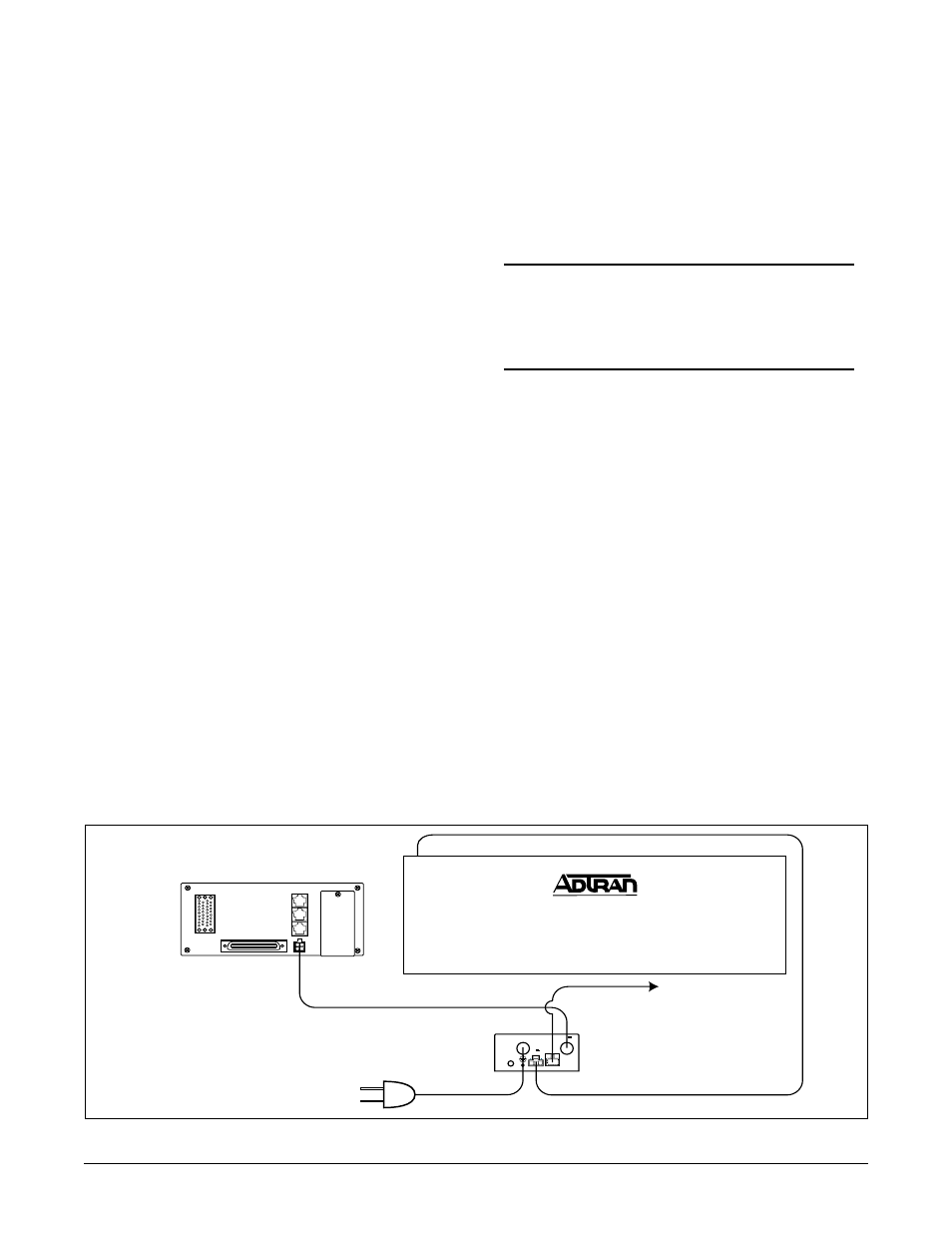
Figure 2. AC/DC Power Supply Battery Charger Layout
3 AMP
-54V ,
2A OUTPUT
120 VAC/
2A 60HZ INPUT
THIS UNIT MAY BE
POWERED BY 2
SOURCES. DISCONNECT
BOTH SOURCES BEFORE
SERVICING.
-48V ,
2A INPUT
AC ALARM
OUTPUT
R1-I
T1-I
R-O
T-O
LX IN
LY IN
EU2
LX OUT
LY OUT
EU1
MLT-A
MLT-B
-48ALM
MJ
MJR
MJV
MJVR
-48 R
P2
-48 V
V.35
T1
FT1
MANAGEMENT
DC
POWER
WARNING:
20 Hz FUSE
MUST BE REMOVED
BEFORE REMOVING COVER.
Terminal
access
cover
To Alarms
TA 750
AC/DC Power Supply
Battery Charging Unit
-48 VDC Backup Battery Pack
-54 VDC Output to TA 750
-54 VDC Battery
Charging/Discharging Line
AC Power Input
WARNING:
SCREW LENGTHS EXCEEDING 3/8"
MAY PUNCTURE BATTERIES
1175044L1
BATTERY BACKUP
P/N: 1175043L2
CAUTION
During TA 750 wall installation,
position the chassis so
front panels face up.