Ecu connection table – Haltech Platinum Sprint RE (HT050900) User Manual
Page 5
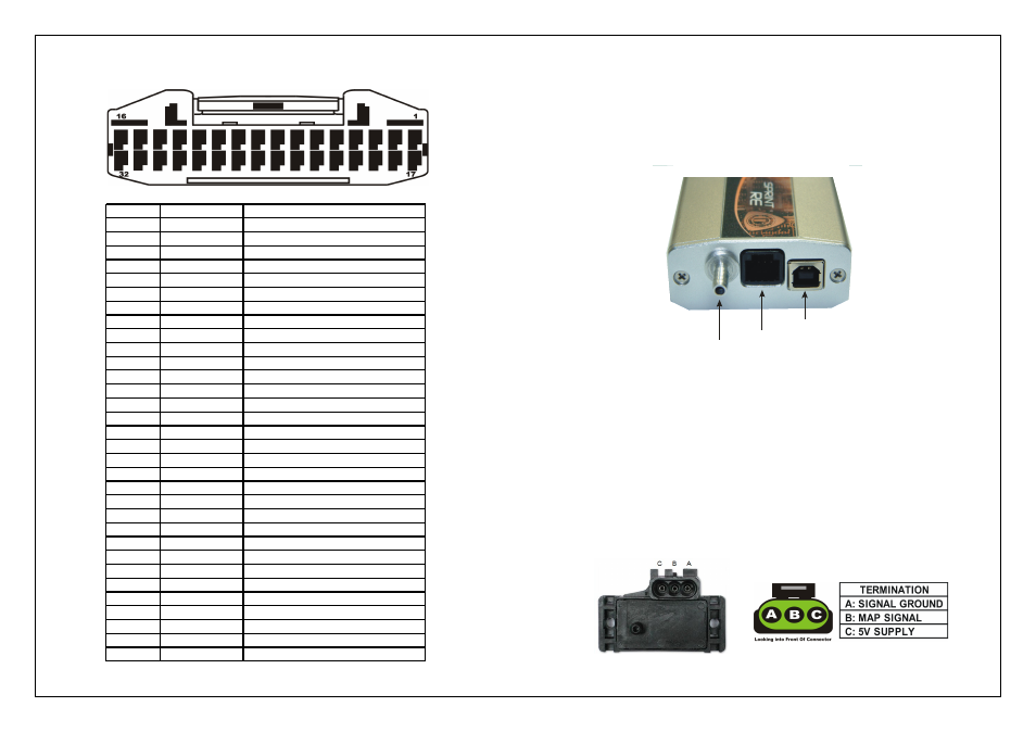
ECU Connection Table
Figure 25 – Platinum Sprint RE Connections table
MAP Sensors
The Platinum Sprint RE ECU's are fitted with an internal MAP sensor rated to 22psi
(150 kPa). Connect the internal sensor to the inlet manifold* via vacuum hose to the
external fitting on the ECU.
* Tap into a high point on the inlet manifold to avoid fuel entering the vacuum line,
as damage to the sensor will occur.
Figure 4 – Internal Map Sensor Fitting
Alternatively an external MAP sensor can be fitted via the harness allowing higher
manifold pressures.
The External MAP sensor when used are usually mounted high on the engine bay
firewall or inner guard using two screws and with the hose nipple facing outwards.
Connect the sensor to the inlet manifold via a short length of vacuum hose and fasten
with either hose clamps or nylon cable ties. Connect the sensor to the main wiring
harness using the appropriate plug and harness branch. Avoid mounting the sensor
below the level of the fuel injectors, because fuel may collect in the vacuum hose and
run down into the sensor. The sensor assembly is weatherproof but it is good practice to
mount the sensor in a protected position away from moisture and heat.
Haltech can supply 1 – 5 Bar Map sensors depending on your application,alternatively
OEM map sensors can be used as long as you have the calibration information to
calibrate the sensor in the ECU Manager Software.
Figure 5 – Manifold Absolute Pressure Sensor and harness Termination
USB CONNECTOR
CAN CONNECTOR
INTERNAL MAP
SENSOR FITTING
Pin #
Wire Colour
Connection
1
Y (4 CORE GY)
TRIGGER ( + )
2
Y (4 CORE GY/B) HOME ( + )
3
-
4
GY
ROADSPEED INPUT (DPI1)
5
-
6
V/B
TACHO OUTPUT (DPO1)
7
V/BR
THERMOFAN OUTPUT (DPO2)
8
V/R
GENERAL PURPOSE OUTPUT 1 (DPO3)
9
V/O
GENERAL PURPOSE OUTPUT 2 (DPO4)
10
GY/R
+12V SWITCHED
11
R
+12V SWITCHED
12
B/Y
FUEL PUMP RELAY TRIGGER
13
L/R
INJECTOR # 4
14
L/BR
INJECTOR # 3
15
L/B
INJECTOR # 2
16
L
INJECTOR # 1
17
G (4 CORE GY)
TRIGGER ( - )
18
G (4 CORE GY/B) HOME ( - )
19
-
20
O/B
AUX REV LIMITER (AVI1)
21
GY/O
O2 SENSOR INPUT
22
B/W
SIGNAL GROUND
23
B
POWER GROUND
24
V
COOLANT TEMPERATURE (ATI1)
25
GY
AIR TEMPERATURE (ATI2)
26
Y
MAP
27
W
TPS
28
O
+5V
29
Y/G
IGNITION OUTPUT # 4
30
Y/O
IGNITION OUTPUT # 3
31
Y/R
IGNITION OUTPUT # 2
32
Y/B
IGNITION OUTPUT # 1