Haltech Platinum Sprint RE (HT050900) User Manual
Page 27
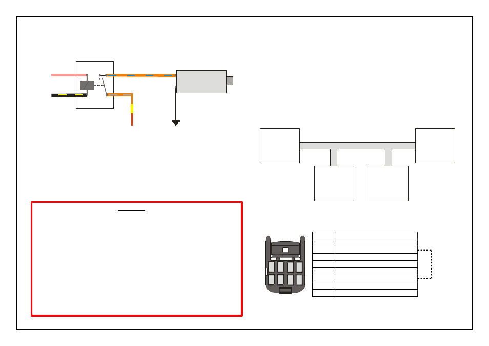
Fuel Pumps
The Black / Yellow wire is used to operate the fuel pump relay. When the Haltech ECU
wants to operate the fuel pump it will close the fuel pump relay which will supply the
fuel pump with 12V From the Battery.
Figure 6- Fuel Pump Wiring
Fuel Pumps continued
It is important that the fuel pump is capable of the correct fuel pressure at full
power, otherwise the engine could be damaged due to a lean fuel mixture. For
example, a 500hp engine requires approximately 210lb/hr for a petrol engine.
The fuel pump must always be mounted lower than the outlet of the fuel tank or
surge tank. Ensure that all care is taken to keep fuel cool. A change in fuel
temperature will change the air/fuel ratio because as fuel temperature increases its
density decreases.
WARNING!
Fuel Injectors
The Platinum Sprint RE is designed to be used with high impedance injectors only.
Injector impedance can be checked using a multimeter. Injector impedance must be
greater than 8 Ohms, if injectors are used that are less than 8 Ohms, excessive current
draw will cause the ECU to cease firing all injector outputs above 1500 RPM.
Fuel injectors are each wired with a 12V supply with the ground being supplied
through the ECU, it is recommended that the supply for the Injectors be wired as
shown in the appendix of this guide, incorporating an injector relay.
The wires labeled as the injector wires will provide the ground to each injector.
When wiring for sequential injection, fuel injectors should be wired with inj 1 output to
Rotar 1 Primary, inj 2 output to Rotor 2 Primary and so on.
Always ensure fuel injector sizing is correct for your application and does not
exceed approximately 80% duty cycle for safe operation.
If low impedance injectors are used, an optional Injector Ballast Resistor Box must be
purchased and installed. Order as Haltech Part # HT020600
CAN Devices
The Platinum Sprint RE ECU can interface directly with selected CAN devices.
CAN connections can be found on the 8 pin rear connector.
A 120 OHM terminating resistor connected between CAN High and CAN Low
terminations may be needed in some applications where the ECU is located at the end
of the CAN Bus.
The ECU is equipped with an internal terminating resistor which can be enabled by
fitting a wire link between pins 2 and 6 of the 8 pin connector.
( Please see example below , connector sold separately Haltech Part # HT030003 )
Wiring Information for our range of data acquisition dashes can be found on our website
Figure 23– Terminating Resistor Example
Figure 24 – Rear CAN Connector (Sold Separately)
1
2
3
4
5
6
7
8
Device
1
Terminating
Resistor
Required
Device
2
Terminating
Resistor
Not Required
Device
3
Terminating
Resistor
Not Required
Device
4
Terminating
Resistor
Required
CAN BUS
Pin #
Function
1
Ground
2
120 Ohm Terminating Resistor Loop
3
CAN LO
4
12V Out
5
Reserved
6
120 Ohm Terminating Resistor Loop
7
CAN HI
8
Reserved
85
87 87
86
30
TO 12V IGNITION SUPPLY
TO - TRIGGER FROM ECU
TO FUEL PUMP + TERMINAL
TO 12V SUPPLY
FUEL PUMP
+
_
TO GROUND
VIA FUEL PUMP FUSE
FUSE
POSITIVE SWITCHED
FUEL PUMP CONTROL
12V FUEL PUMP RELAY