Haltech Platinum Sprint RE (HT050900) User Manual
Page 17
3
rd
Generation RX7 (FD3S)
Wiring
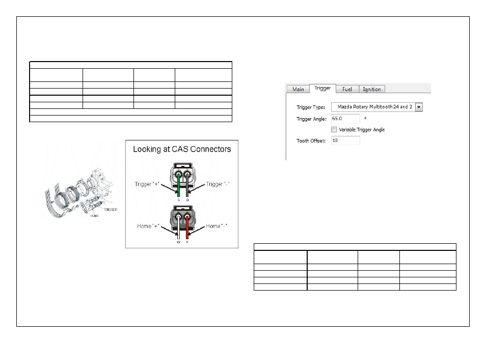
The wiring for this type of trigger is as follows:
Figure 15- 3
rd
Generation Crank Angle Sensor Location and wiring
3
rd
Generation RX7 (FD3S)
Settings
Below is the setup required for your engine
Please Note:
Trigger Angle may need to be altered slightly when checking the
base ignition timing.
On the 3
rd
Generation 13B, the crankshaft pulley timing mark only
exists at -20 deg BTDC for Trailing #1.
Figure 16- 3
rd
Generation ECU Manager Trigger Settings
Fuel Setup
Wiring
All injectors share a common +12V supply voltage.
The ECU injector output completes the circuit to ground when fuel delivery is required.
When wiring for sequential fuel injection, fuel injectors should be wired as follows:
Settings
*Please refer to the Fuel Setup in the user manual for information regarding fuel system
settings
Trigger "+"
1
*Yellow
Green Wire
Home "+"
2
**Yellow
White Wire
Trigger "-"
17
*Green
Black Wire
Home "-"
18
**Green
Red Wire
* Denotes core colour inside Grey 4 core shielded cable
* *Denotes core colour inside Grey / Black 4 core shielded cable
Trigger / Home
Input
Haltech ECU Pin
Number
Wire Colour
Crank Angle Sensor
Connection
3rd Generation RX7 (FD3S) Crank Angle Sensor Wiring
Injector # 1
16
Blue
Rotor # 1 - Primary
Injector # 2
15
Blue / Black
Rotor # 2 - Primary
Injector # 3
14
Blue / Brown
Rotor # 1 - Secondary
Injector # 4
13
Blue / Red
Rotor # 2 - Secondary
3rd Generation RX7 (FD3S) Fuel Injector Wiring
Injector Output
Haltech ECU Pin
Number
Haltech
Wire Colour
Engine Connection