Haltech ecu, Cdi unit – Haltech Platinum Sprint RE (HT050900) User Manual
Page 26
ECU Manager / ECU Manuals
Detailed manuals can be found in the software by pressing your F1 key or by
selecting the Help tab located at the top left of the screen.
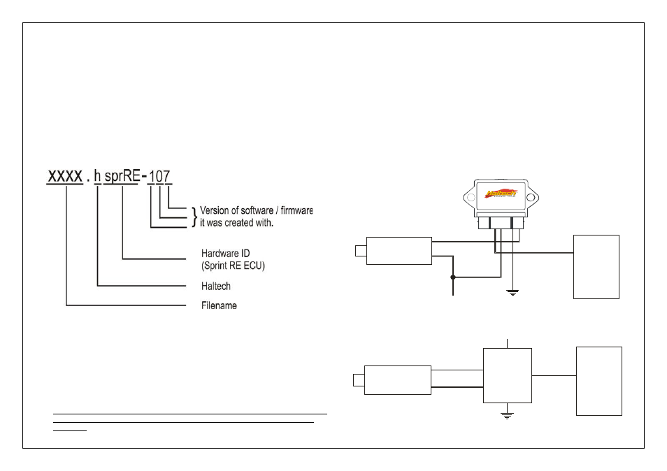
ECU Manager File Extensions
When ECU manager saves the map from the Haltech ECU, it saves the map with
a Haltech specific file extension.
The File extension can be broken down as follows:
Example File : xxxx.hsprRE -107
Later map versions cannot be loaded into ECU's with earlier firmware versions.
ECU Manager will upgrade earlier map versions when loading into ECU's with later
firmware versions.
ECU Manager upgrades maps between versions where equivalent settings are
available. However, new settings not in the original map, will be substituted with
values from the new version's default map.
Whenever ECU Manager converts your ECU map, you should always check your
map settings to ensure that all the appropriate settings have been converted
correctly.
Ignition Outputs
The Platinum Sprint RE ECU cannot control the ignition coils directly.
Some sort of ignition amplifier such as a power transistor, Haltech ignition module or
high intensity spark unit (CDI unit eg MSD 6A, crane HI6, M&W pro12 etc) must be used
to interface the ECU with the coils. This ignition module supplies the ground to the
coil only when the ECU directs it to – each coil also requires a 12V source (with the
exception of CDI units where the 12V will often come from the CDI unit itself).
Many factory cars will have ignition modules external to the ECU.
These factory modules can be used in conjunction with the Platinum Sprint RE ECU.
The ignition output wires from the Platinum Sprint RE wire harness should be used to
trigger the ignition amplifier – when wiring the ignition amplifier ensure that the system is
wired in cylinder order for direct fire ignition setup or in order of the outputs for waste
spark setup. (ie Ign 1 will fire first, then Ign 2 will fire next etc until the last ignition
channel is reached regardless of engine firing order.)
Figure 7 – Ignition Wiring using Haltech Ignition Module
Figure 8– Ignition Wiring Using CDI Unit
1. COIL NEGATIVE #1
2. CHASSIS GROUND
3. N/A
4. +12V IGNITION
5. ECU IGNITION OUTPUT #1
6. N/A
7. N/A
HALTECH
HECU1
7 6 5 4 3 2 1
+
-
+12V SWITCHED
GROUND
Haltech HECU1 Pinout
HALTECH 1 CHANNEL IGNITION MODULE
HALTECH
ECU
IGN 1
COIL # 1
+
-
+12V SWITCHED
GROUND
HALTECH
ECU
IGN 1
COIL # 1
CDI UNIT