PerTronix Ignitor II 91589 User Manual
Page 2
WIRING INSTRUCTIONS
The Ignitor II ignition can be used in conjunction with most ignition coils rated
1.
at 0.45 ohms or greater. For optimum performance purchase and install the
Flamethrower II high performance coil.
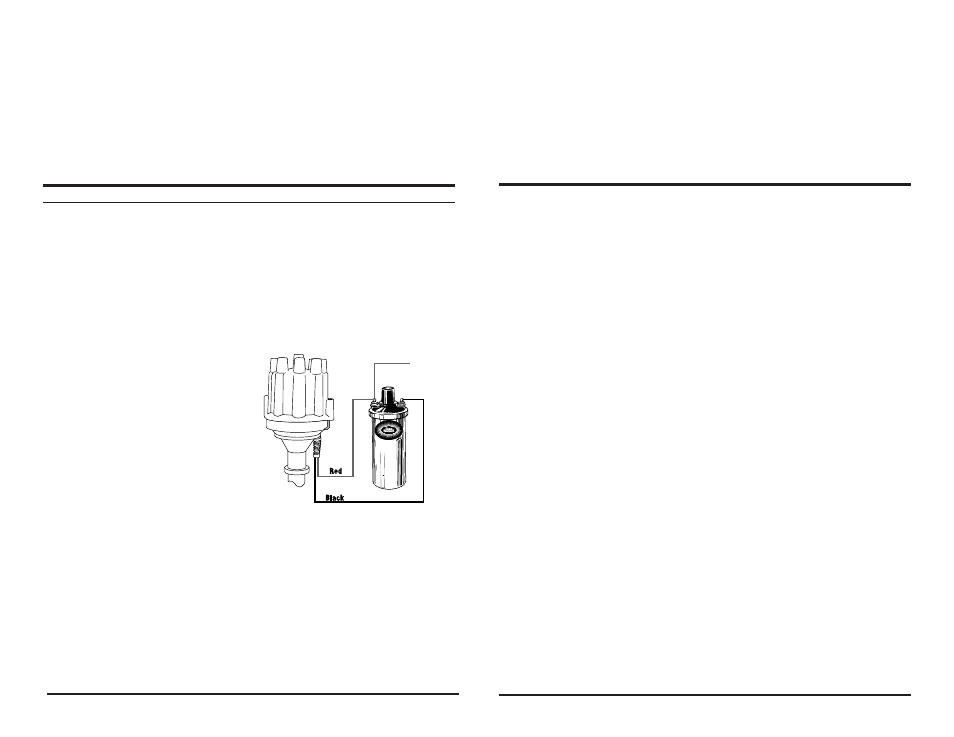
Attach the black Ignitor II wire to the negative coil terminal. Attach the red
2.
Ignitor II wire to the positive coil terminal. (See Figure 1)
A. Recommended Installation: Many vehicles came equipped with ballast resistor or
resistance wire. To achieve optimum performance from the Ignitor II ignition system,
we recommend removal of these components.
To remove a ballast resistor, (normally
•
white ceramic blocks 3 to 4 inches
long), disconnect all wires on both
ends of the ballast resistor. Remove the
resistor from the vehicle and splice the
disconnected wires together at a single
point.
To remove a resistance wire, trace the
•
coil power wire, which was previously
connected to the positive coil terminal,
back to the fuse block. Bypass this wire
with a 12-gauge copper stranded wire.
B. Alternative Installation: The Ignitor II
can also be installed in applications retaining the ballast resistor or resistance wire.
Attach the Ignitor II black wire to the negative coil terminal. Attach the Ignitor II
•
red wire to the ignition side of resistance, or any 12 volt ignition power source.
Check to insure that the polarity is correct, and that all connections are tight.
3.
Re-connect the battery.
4.
Start the engine and allow it to reach normal operating temperature. Check
5.
ignition timing, and adjust to the desired setting.
4O
COMMON QUESTIONS AND ANSWERS
Q. The engine will not start or runs rough. What is the problem?
A. Check all connections to insure that they are tight, and in the proper location. Check all grounds; if a
distributor ground wire was removed make sure that it was reattached properly. Make sure that the red
Ignitor II wire is supplied with a full 12 volts. The Ignitor II is designed to sense high current levels, and
shut off before damage occurs. Check all wires for shorts, correct polarity and that the ignition coil’s
primary resistance level is acceptable.
Q. The vehicle will start, but then die. After waiting it will start again. What is wrong?
A. The Ignitor II may have a “Low Voltage Problem.” If the voltage supplied to the red Ignitor II wire
is insufficient, the system may run for a period of time, and then shut down as the voltage drops due
to engine heat. The period may vary from minutes to hours depending on available voltage and wiring
condition. To remedy this condition refer to steps 2-4 of the wiring instructions.
Q. How do I check for a “Low Voltage Problem” or determine if I am getting adequate voltage?
A. To quickly test for a “Low Voltage Problem” or for adequate voltage, remove the Ignitor II red wire
from the coil positive terminal. Attach a jumper wire from the battery positive terminal to the Ignitor
II red wire. Try to start the vehicle. If the vehicle starts with this test refer to steps 2-4 of the wiring
instructions for further information.
Q. How do I check my coil for primary resistance?
A. Remove all wires from the coil. Set the ohmmeter to the lowest scale. Attach one lead of the meter to
the positive coil terminal. Attach the other lead to the negative coil terminal. The Ignitor II is compatible
with coils having a resistance of 0.6 ohms or greater.
Q. May I modify the length of the wires?
A. Yes, you may cut the wires to any length your application requires. You may also add lengths of wire if
needed (20-gauge). Make sure that all wire splices are clean and the connections are tight.
Q. Will the Ignitor II work with aftermarket capacitive discharge boxes?
A. Yes, the Ignitor II is compatible with most CD boxes in the same respect as points. Use the CD box
wiring instructions for point systems and treat the Ignitor II black wire as a point wire. The Ignitor II red
wire should be attached to the 12-volt power source.
Q. Will the electronic shift assist in an OMC boat work with the Ignitor II?
A. The Ignitor II will work with all OMC stern-drive applications, when our “diode fix” is used. If you’ve
purchased a kit that didn’t include the “diode fix” diagram, call our tech line.
Q. How can I receive additional help?
A. Check our web site for current trouble shooting tips and up to date technical information. Log on to
www.pertronix.com. You may also contact our tech line at (909-547-9058)
FIGURE 1
(WITHOUT EXTERNAL RESISTOR)