Spektrum SPMAR6310 User Manual
Page 7
EN
7
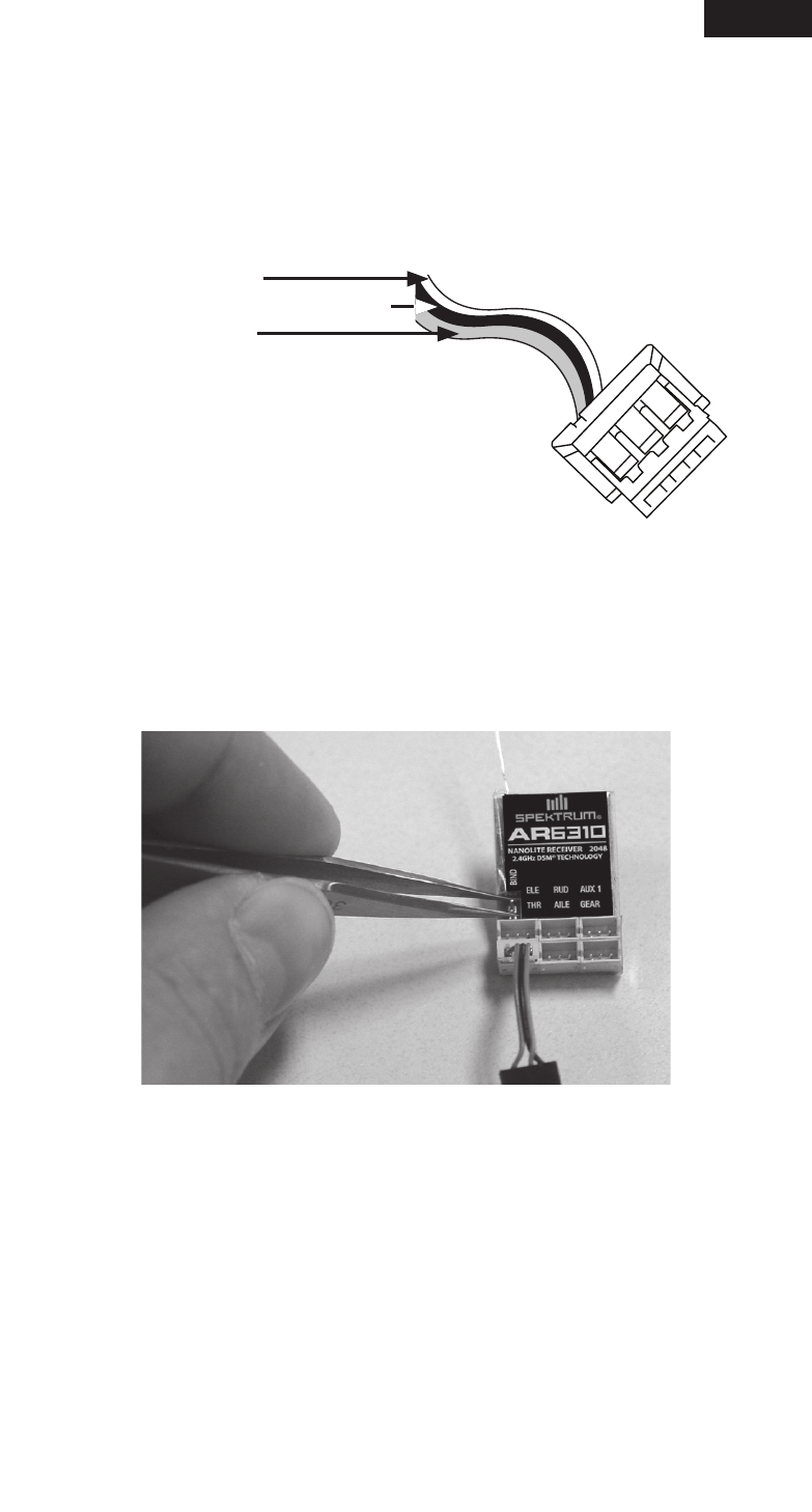
Servo Connectors
The AR6310 uses JST B3B-ZR micro connectors offering the lightest and most
compact installation. Note that servos must have micro JST-type connectors to
be compatible with the receiver. Note that some JST-type servos have a different
polarity than Spektrum servos. Plug the servo leads into the appropriate servo
ports in the receiver noting the polarity of the servo connector. See photo for
correct connector polarity.
Binding
The AR6310 receiver must be bound to the transmitter before it will operate. Bin-
ding is the process of programming the receiver to recognize the GUID (Globally
Unique Identifier) code of a single specific transmitter.
1. To bind an AR6310 to a DSM2/DSMX transmitter, power off the receiver and
short the bind pins together with tweezers, hemostats or small needle-nose
pliers.
2. Power on the receiver. If the receiver is installed in an electric aircraft, turn on the
speed controller to power up the receiver. If the receiver is going to be powered
by a separate battery, plug the battery into any unused port. The amber light will
blink, indicating the AR6310 is in bind mode.
3. Position the transmitter’s control sticks and switches in the desired failsafe
positions (normally low throttle and all other controls at neutral).
4. Follow the procedures of your specific transmitter to enter Bind Mode; the
system will connect within a few seconds. Once connected, the LED on the
receiver will turn solid, indicating the system is connected.
5. After you’ve set up your model, it’s important to rebind the system so the true
low throttle and neutral control surface positions are set.
Red Wire: Positive
Brown Wire (middle wire): Negative
Orange Wire: Signal