Installation, Plumbing connections – Blodgett BC-20G User Manual
Page 10
6
Installation
Plumbing Connections
WaTER COnnECTIOn
NOTE: Hot water maximizes steam production but is not
required. Cold water may be supplied to both in-
lets if hot water is not available.
Connect the appliance to quality cold water via a pressure
hose with 3/4” (1/9 cm) couplings. Cold water is connect-
ed to the left solenoid/pressure regulator as viewed from
the rear of the oven. Hot water connection, right solenoid/
pressure regulator, to the boiler is recommended. A shut
off valve must be provided adjacent to the oven.
NOTE: Hot water must not be applied to the cold water
inlet.
1/2” Appliance Hose with 3/4”
Hose Fittings
Figure 1
WaRnInG!!
The use of poor quality water will invalidate
your warranty.
This product must be installed by a licensed Plumber or
Gas Fitter when installed within the Commonwealth of
Massachusetts.
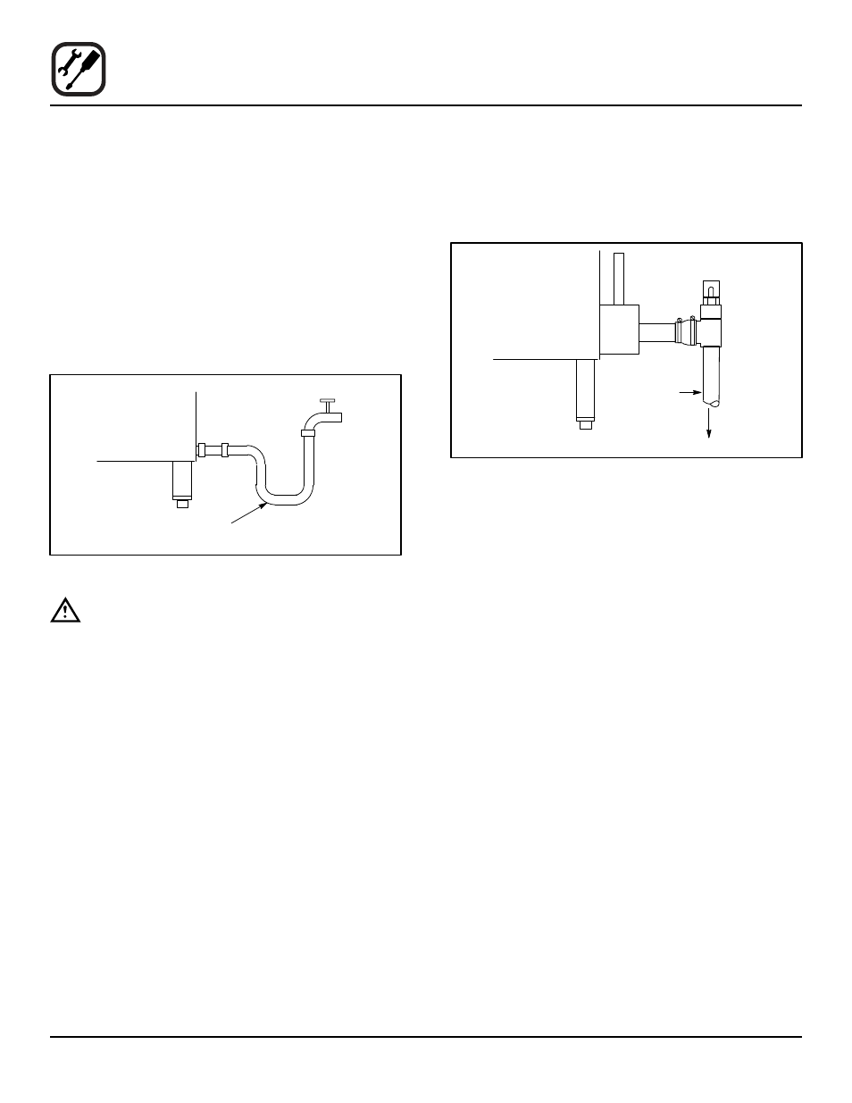
dRaIn COnnECTIOn
A 2” (5 cm) copper pipe with standard drain pitch must
be run to an open drain or connected to a standpipe
equipped with a vent.
NOTE: The waste water can also be directed to a nearby
floor drain. Flexible hose which allows trapped
water to accumulate in sagged runs must be
avoided.
1. Find the drain connection on the lower rear of the unit.
2. Loosen the coupling clamps. Attach a 2” (5 cm) cop-
per drain pipe to the drain connection. Retighten the
coupling clamps.
NOTE: The open end of the drain should be installed
facing the floor. Copper line, used for installation
to an open drain or floor sink, must be supplied
by the installer.
Use of a trap inline will cause
drain backup.
2” Drain
Customer
Supplied
To Drain
Oven Drain
Figure 2
Specific water/drain connection for City of Los Angeles
1. Each drain line from the appliance shall be routed
without dips or sags to terminate above the flood level
rim of an approved indirect waste receptor.
2. The appliance shall be installed in accordance with
the manufacturer’s printed instructions and the LAPC
and LAMC, 1999 editions.
3. A backflow protection device may be required by lo-
cal codes. If so, install on the potable water system
directly ahead of the appliance. The backflow protec-
tion device shall be any of the following: an approved
pressure type vacuum breaker installed at least 12”
above the highest point of use, a double check valve
backflow preventer or a reduced pressure principal
backflow preventer.