Installing the media converter, Planning the installation, Cabling specifications – Allied Telesis AT-MC1001SC/GS4 User Manual
Page 20: Planning the installation cabling specifications
10
Installing the Media Converter
The following sections explain how to install the media converter. The media
converter can be installed on a table or in an AT-MCR12 chassis.
Planning the Installation
Be sure to observe the following guidelines when planning the installation of
your media converter.
❑
The nodes connected to the media converter must operate at 1000
Mbps.
❑
The two nodes connected to the ports of the media converter must
operate with the same duplex mode, either half- or full-duplex. The
media converter itself can operate in either mode.
❑
The devices connected to the two ports on the media converter can be
network adapter cards, repeaters, switches, or routers.
❑
Be sure to observe the cabling specifications. Refer to “Cabling
Specifications” below.
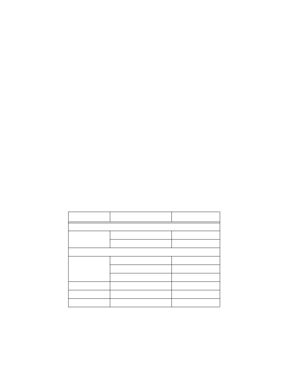
Cabling Specifications
Table 3 list the IEEE 802.3u cabling specifications for the AT-MC1001 Series
Media Converters.
Table 3 Cabling Specifications
Port
Cable Type
Maximum Distance
1000Base-SX
All Models
62.5/125
µ
m multimode fiber
275 m (902 ft)
50/125
µ
m multimode fiber
550 m (1,804 ft)
1000Base-LX
AT-MC1001
62.5/12 5
µ
m multimode fiber
550 m (1,804 ft)
50/12 5
µ
m multimode fiber
550 m (1,804 ft)
10/125
µ
m single-mode fiber
10,000 m (32,800 ft)
AT-MC1001/GS2
10/125
µ
m single-mode fiber
20 km (12.4 mi)
AT-MC1001/GS3
10/125
µ
m single-mode fiber
50 km (31 mi)
AT-MC1001/GS4
10/125
µ
m single-mode fiber
70 km (43.4 mi)