R.p.s. output connector specifications – Allied Telesis AT-RPS8000 User Manual
Page 14
8
R.P.S. Output Connector Specifications
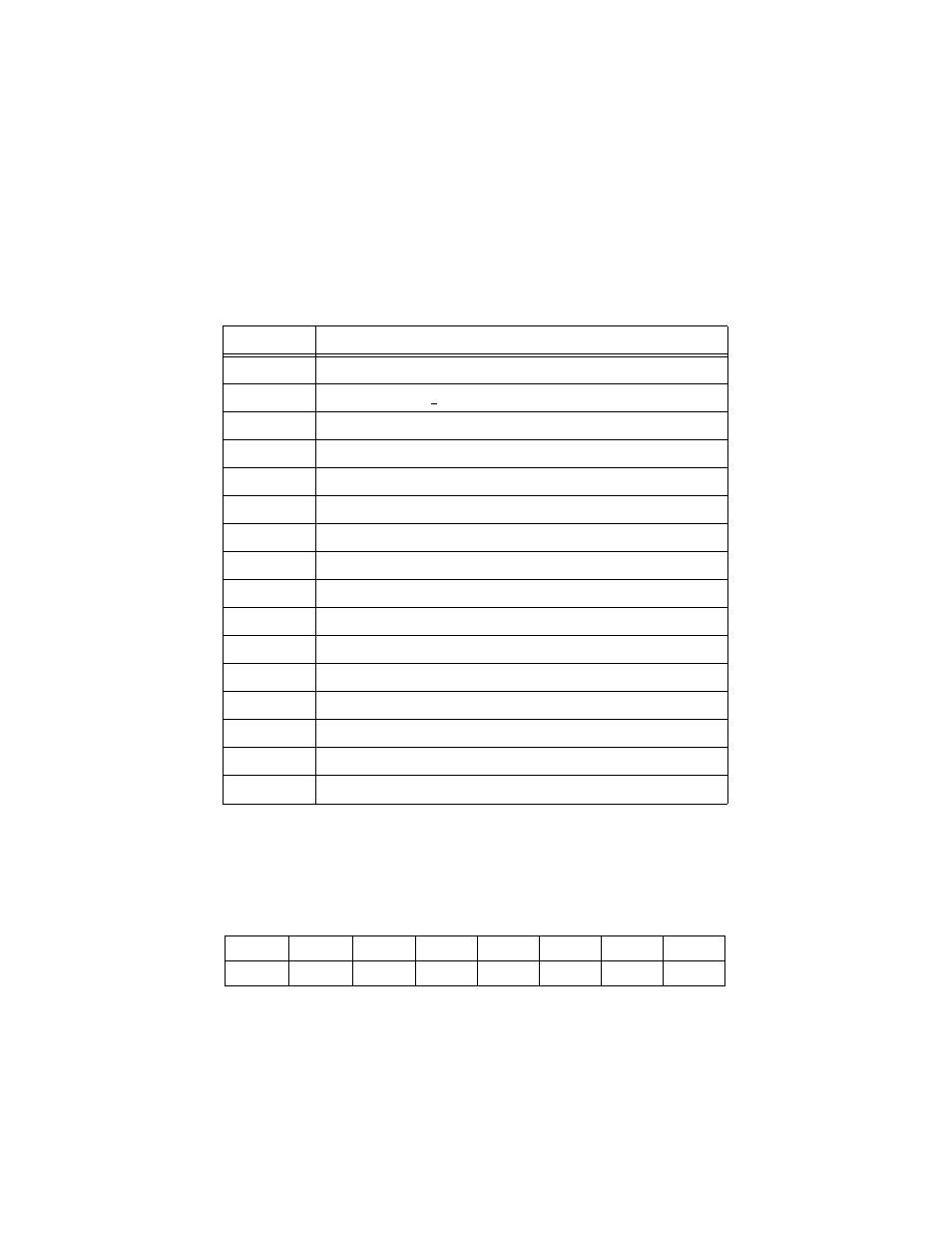
Table 1 shows the pin assignments for the R.P.S. Output connectors located on
the back panel of the AT-RPS8000 unit.
Table 1 R.P.S. Output Connector Pin Assignments
Table 2 shows the pin numbering for the R.P.S. Output connector. Pin numbers
1 through 8 are the bottom row on the connector with pin 1 in the bottom right
corner. Pin numbers 9 through 16 are the top row with pin 9 in the top right
position on the connector.
Table 2 AT-RPS8000 Output Pin Layout
Pin Number
Function
1
+12V dc
2
Remote Sense (RS) +5V dc
3
RS Ground
4
RS +3.3V dc
5
Redundant Power Supply (RPS) present
6
Ground (+3.3V dc Return)
7
Ground (+5V dc Return)
8
+5V dc
9
Ground (+12V dc Return)
10
+3.3V dc
11
Ground (+3.3 dc Return)
12
+3.3V dc
13
Ground (+3.3V dc Return)
14
+3.3V dc
15
+5V dc
16
Ground (+5V dc Return)
16
15
14
13
12
11
10
9
8
7
6
5
4
3
2
1
- AT-GS908M (54 pages)
- AT-x230-10GP (80 pages)
- AT-GS950/48PS (64 pages)
- AT-GS950/10PS (386 pages)
- AT-GS950/16PS (386 pages)
- AT-GS950/48PS (386 pages)
- AT-9000 Series (258 pages)
- AT-9000 Series (1480 pages)
- IE200 Series (70 pages)
- AT-GS950/48 (410 pages)
- AT-GS950/8 (52 pages)
- AT-GS950/48 (378 pages)
- AT-GS950/48 (60 pages)
- SwitchBlade x8106 (322 pages)
- SwitchBlade x8112 (322 pages)
- SwitchBlade x8106 (240 pages)
- SwitchBlade x8112 (240 pages)
- AT-TQ Series (172 pages)
- AlliedWare Plus Operating System Version 5.4.4C (x310-26FT,x310-26FP,x310-50FT,x310-50FP) (2220 pages)
- FS970M Series (106 pages)
- 8100L Series (116 pages)
- 8100S Series (140 pages)
- x310 Series (116 pages)
- x310 Series (120 pages)
- AT-GS950/24 (404 pages)
- AT-GS950/24 (366 pages)
- AT-GS950/16 (44 pages)
- AT-GS950/16 (404 pages)
- AT-GS950/16 (364 pages)
- AT-GS950/8 (404 pages)
- AT-GS950/8 (364 pages)
- AT-GS950/8 (52 pages)
- AT-8100 Series (330 pages)
- AT-8100 Series (1962 pages)
- AT-FS970M Series (330 pages)
- AT-FS970M Series (1938 pages)
- SwitchBlade x3106 (288 pages)
- SwitchBlade x3112 (294 pages)
- SwitchBlade x3106 (260 pages)
- SwitchBlade x3112 (222 pages)
- AT-S95 CLI (AT-8000GS Series) (397 pages)
- AT-S94 CLI (AT-8000S Series) (402 pages)
- AT-IMC1000T/SFP (23 pages)
- AT-IMC1000TP/SFP (24 pages)
- AT-SBx3106WMB (44 pages)