Installing additional at-pwr8000 modules – Allied Telesis AT-RPS8000 User Manual
Page 12
6
8.
Turn on the AT-RPS8000 using the switch on the back panel of the
unit. (Refer to Figure 4 for the ON/OFF switch.)
9.
Make sure the LED on the front of the AT-PWR8000 module is solid
green.
10. Make sure the RPS LED on the front of the Ethernet switch is solid
green to indicate a good connection to the AT-PWR8000 module.
Installing Additional AT-PWR8000 Modules
The AT-RPS8000 can supply redundant power for up to four Ethernet
switches. Initially, it contains one pre-installed AT-PWR8000 module. You
can purchase additional power modules from your Allied Telesyn
representative. Each additional AT-PWR8000 module comes with a DC
power cord.
To install additional AT-PWR8000 modules, perform the following steps.
Note
It is not necessary to power OFF the AT-RPS8000 unit or the
connected Ethernet switches to install a new AT-PWR8000 module.
1.
Remove the AT-PWR8000 module from the shipping package and
store the packing material in a safe place.
2.
Remove the blank faceplate from an empty expansion slot from the
front of the AT-RPS8000 unit by unscrewing the two captive screws
with a Phillips screwdriver.
3.
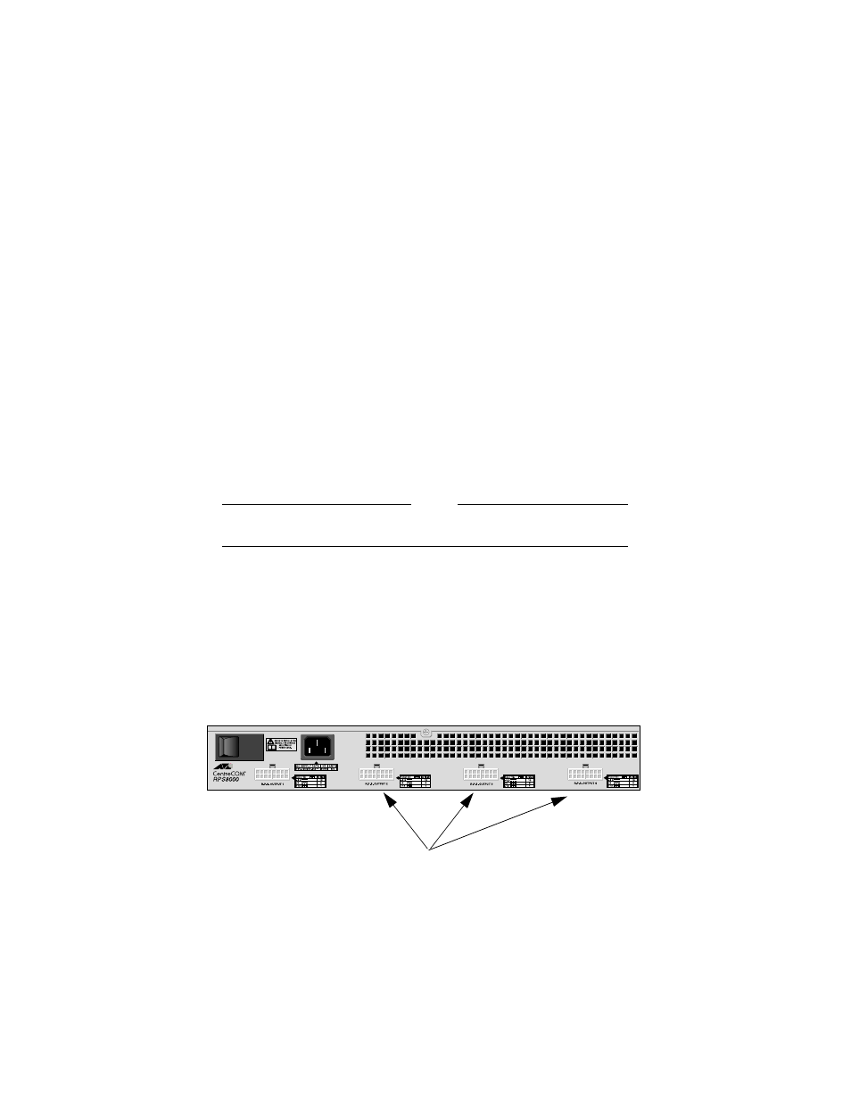
Attach one end of the provided DC power cord to the connector on the
back panel of the AT-RPS8000 unit, directly behind the faceplate you
just removed. (Refer to Figure 6 for the DC connectors.)
Figure 6 DC Connector Locations
DC Power Connectors